[N-World Contents] [Book Contents] [Prev] [Next] [Index]

File and Edit Menus (cont.)


Creating Polyhedra Using Sketched Wires

A number of polyhedra can be generated using a technique called sketching. Sketching involves drawing one or more wires, and generating shapes in different ways using those wires. Each of the polyhedra described in this section use sketched wires.

Solid of Rotation

File>New Object>solid of rotation builds a solid of rotation (sometimes referred to as a "lathe" operation).

A solid of rotation is an object created by sketching the silhouette of the desired object from top to bottom, then sweeping that silhouette around either the vertical or horizontal axis to describe the object.

Figure 2.35 Typical solid of rotation (created with wire shown at right)

Note! The silhouette should lie entirely to one side of the axis of rotation so that the generated solid of rotation does not intersect itself.

Tube

File>New Object>tube builds a tube shaped object.

A tube is a polyhedron created by sweeping a cross section along a path defined by a wire or sketched contour. The cross section can be automatically generated, radially symmetric (circular), drawn by hand, or derived from a pre-existing wire.

Figure 2.36 Tube parameters

Note that these sketching parameters are the same ones used when creating a tube solid, lamina, or contour solid. The procedures for creating each of these types of objects appear below.

Figure 2.37 A wire (top) and a tube made with a circular cross-section

Figure 2.38 A second wire encoded for use as the contour

(CLICK-R) on Tube to select the path along which you want to pass the cross-section.

Then choose a cross section of type Arbitrary and specify that the cross section is to come from a Previous wire. (CLICK-L) in the C.S. object text box to select the cross section wire to move along the path wire:

Figure 2.39 The finished tube (with end faces selected to show the tube's shape)

Tube Solid

File>New Object>tube solid creates a tube solid, which resembles a tube in that a silhouette or contour is swept along a path, but instead of the contour being closed (creating a cross section), the whole swept area is enclosed by connecting the beginning and end of the path and creating top and bottom faces, like a contour solid.

To build a tube solid, start by encoding the contour wire:

Figure 2.40 The contour wire

Next, sketch the path wire. Make sure that the silhouette wire is perpendicular to the path wire. (If you sketch the wire, you can use Rotate to make it lie in the correct plane). Give the wires descriptive names (such as "silhouette" and "path") so you know which wire you are using when executing the solid:

Figure 2.41 The contour and path wires

Note. The path wire should lie on a single plane; otherwise the generated top and bottom faces of the tube are likely to be twisted.

Next, (CLICK-R) on Tube Solid. You are prompted to select the path wire. In the dialog box that opens, choose Previous, then specify the contour wire to pass along the path in the Contour object text edit box.

The tube solid parameter menu

Imagine that the contour wire defines half of a shaper bit moving along a solid defined by the height of the contour wire:

The contour wire moves along the path wire, much like a bit

Contour Init Rot determines the initial angle or rotation at which the bit is "applied" (the default of 0 keeps the bit perpendicular). The resulting tube solid looks like this:

The contour passes along the path wire; faces are created along the top and bottom of the path to create a tube solid

Lamina

File>New Object>lamina sketches a contour, which is then made into a flat, double-sided polyhedron.

Figure 2.42 Wire

Figure 2.43 Wire converted into lamina and extruded

Contour Solid

File>New Object>contour solid creates a contour solid polyhedron. A contour solid is created by scaling the cross section out to the contour. First create the path wire:

Figure 2.44 How the contour and cross section combine to form a contour solid

Next, create the wire that you'll use as the contour solid. If you create it ahead of time, you'll need to rotate it so it's perpendicular to the path wire:

Figure 2.45 Path and cross-section wires for contour solid

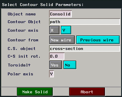
Next, (CLICK-R) on Contour Solid. You are prompted to select the path wire. In the dialog box that opens, choose Previous wire, then specify the cross section to pass along the path in the C.S. object text edit box.

Figure 2.46 Contour solid menu parameters

(CLICK-L) on Make Solid to generate the final contour solid:

Figure 2.47 Finished contour solid

Wires & Trajectories

Wires and trajectories can be created by manually specifying, or encoding, the coordinates of each node on the object. (CLICK-L) on the wire or trajectory options of the New Object menu, depending on which type of element you want to create:

When encoding wires or trajectories, mouse clicks work as follows:

Table 2.3 Mouse behavior when encoding wires
Mouse action Description
(CLICK-L)

Creates a new point.

(SHIFT-L)

Acts differently depending on the type of object being encoded:

For a polyhedron, it connects a line to the nearest old point (which is
highlighted).

For a wire, it undoes the last segment.

(CTRL-L)

Creates a new control point for a nurb curve.

(ALT-L)

Starts an arc.

(HOLD-M)

Adjusts the location of the cursor in the z axis.

(CLICK-R)

Acts differently on the type of object being encoded:

For a polyhedron, it closes the current face by creating an edge
between the last and first vertices.

For a wire, it finishes the operation.

(SHIFT-R)

Displays the Encoding Options menu, which is how you exit from
encoding mode.

(CTRL-R)

Halts encoding temporarily to let you execute one N-Geometry command before returning to encoding. (This is useful for moving the location of the camera.)

Encoding Options

To display the following menu of encoding options, (SHIFT-R) while encoding. (This menu comes up only after you have entered the sketch editor, described below.)
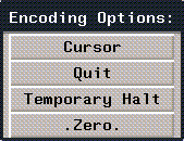
Figure 2.48 Encoding Options menu

Cursor

Modifies the shape and characteristics of the cursor used when encoding:
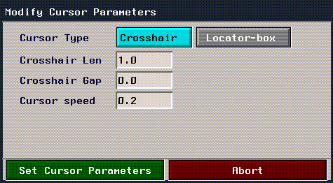
Figure 2.49 Setting cursor parameters

Figure 2.50 Crosshair cursor

Figure 2.51 3-arm locator

Figure 2.52 Half-box locator

Figure 2.53 Full-box locator

Quit

Ends the encoding session and returns to the top level of N-Geometry.

Temporary Halt

Halts encoding for one command. (This is useful if for when you want to move the camera.)

Zero

Resets the cursor position, depending on which mouse button you click:

Patch Body

Patch bodies are a way of representing shapes using splines rather than polyhedra. N-Geometry supports the creation of patch bodies using a "control" polyhedron object. To make changes to the patch body, you manipulate the original polyhedron, and the changes are automatically reflected in the patch body.

Patch bodies are better at representing smoothed surfaces because it uses curves to describe a surface rather than polyhedra; and because patch bodies are described by curves, you can render an object at essentially any distance from the camera with no appreciable change in quality.

To create a patch body:

1. Create a polyhedron (such as an octahedron).

Because patch bodies work better for smoother objects, you may want to use the Smooth operation on any object for which you generate a patch body.

Figure 2.54 Smoothed octahedron

2. (CLICK-L) on File>New Object>patch body.

You are prompted to select the control object from a list of objects that currently exist in the scene.

The generated patch body approximates the shape of the polyhedron, but is a lighter gray (if you are using the default color scheme).

Figure 2.55 Patch body for octahedron

To change the shape of the patch body, you manipulate the controlling polyhedra (or other N-Geometry object).

Grid

(CLICK-L) on File>New Object>grid brings up a Select Grid Parameters menu:
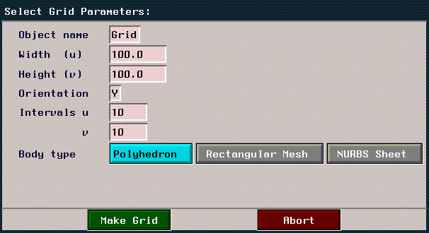
Figure 2.56 Grid parameters menu

Parameters for generating a grid are shown below:

Table 2.4 Grid parameters
Parameter Type Description
Name

The name of the grid object.

Width & Height

The overall dimensions of the grid, expressed in global units.

Orientation

The axis to which the plane is perpendicular.

Intervals

Number of faces the grid should be divided into on the given axis.

Body type

Type of grid to generate.

Polyhedron

Generates an object whose "front" or top side is divided into the specified number of faces. (The back side remains a single face unless manually cut.)

Rectangular Mesh

Generates a mesh; that is, the apparent grid is actually a group of joined segments with no faces. This is much like a net.

The rectangular mesh grid looks like a polyhedral grid but has only nodes and segments, as does a wire. The grid has no faces and has a constant number of segments in either dimension. For example, if you cut one of its segments, a rectangular mesh grid automatically cuts all the other segments in that row in an identical fashion.

Note. You can make a splined surface grid from a rectangular mesh by selecting the mesh, then choosing the Make Splined Surface command. (See "Make Splined Surface," on page 4-60.)

NURBS Sheet

Generates a non-uniform rational B-spline (NURBS) mesh.

The mesh functions much as a control polyhedron when working with a patch body. NURBS sheets are useful in that the curved surface can be manipulated directly.

If you create a NURBS sheet, Degree specifies the method used to generate the splined surface (the lower the number specified, the more closely the spline surface follows the polyhedral surface):

Figure 2.57 A polyhedral grid

Text

N-Geometry comes with a wide variety of pre-installed fonts from which you can generate 3D text characters.
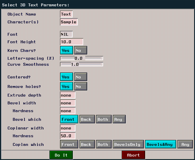
Selecting File>New Object>text brings up the Select 3D Text Parameters menu. If you don not have the Logo Utilities Item selected in the Utilities>Preferences menu, only a subset of the items on the following menu will appear:

Figure 2.58 3D text parameters menu

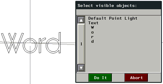
When you create a text string, N-Geometry creates a separate object for each character; each "character" object is automatically restructured under the "word" object.

Figure 2.59 Structure for word object-each letter is a subobject under the word object

This gives you the ability to animate either the word or individual characters when animating in N-Dynamics.

Table 2.5 Text parameters
Parameter Subparameter Description
Object Name

The top-level name of the text object.

Characters

The characters to create. Each character is a separate body and is inferior to the top-level text object.

Font

Character font. The default font is the first available loaded font, if any. (CLICK-L) and choose New to select the font to use when generating the text.

Font Height

Specifies the font height (in global units).

Kern chars?

Compensates for wide and narrow characters by setting extra space around wide characters and setting less space around narrow characters.

Letter-spacing%

Adjust the amount of space between all characters as a percentage of the font height.

Curve
Smoothness

The factor to determine subdivision of arcs along the edge of a letter

Centered?

Centers the created text string around the object's center.

Remove holes?

Automatically deholes any faces. See "Dehole," on page 4-25 for more information.

Extrude depth

The "depth" of the created text characters, expressed in global units.

Bevel Width

Creates beveled letters. Selected edges (specified with Bevel which? below) are "sanded down"by the amount specified here (in global units). A higher value bevels the edge more.

Hardness

Specifies the hardness of edges to be selected (perpendicular edges have a hardness of 90 degrees. Higher values select edges closer to perpendicular.

Bevel which?

Specifies which edges are beveled:

Front bevels only those edges on the front of the letter.

Back bevels only those edges on the back of the letter.

Both bevels edges on the front and back.

Any bevels edges on the front, back, and any edges created when the letter is extruded (if any new edges are created).

Coplanar width

Create coplanars around the edges of the letter. The edges (specified below) are coplanared by the amount specified here (in global units).

Hardness

Specifies the relative "harshness" of the coplanaring effect.

Coplanar which?

Specifies which edges are coplanared:

Front creates coplanars along the edges on the front of the letter.

Back creates coplanars along the edges on the back of the letter.

Both creates coplanars along the edges on the front and back.

Bevels Only creates coplanars only on beveled edges.

Bevels & Any creates coplanars on beveled, front, back, and any edges created with an extrude operation.

Any creates coplanars on any edges except those created as a result of the specified bevel.

Default generated characters are laminae and can be manipulated just like any other object. However, the number of operations you can use with faces with holes is limited. (Refer to the section "Faces with Holes," on page A-1.)

Figure 2.60 Some sample text

Image

The File>New Object>image command lets you create a wire or lamina by converting the outline of an image (or a matte channel) in N-Paint into an object in N-Geometry.

To use this operation:

1. In N-Paint, make the image from which you want to generate the object(s) your current image.

Figure 2.61 Make the image you want to generate the laminae from the current image

2. In N-Geometry, (CLICK-L) on File>New Object>Image.

The following dialog box appears:

Figure 2.62 Using an image to create an object

3. After selecting the parameters used to generate the laminae, (CLICK-L) on the Make Body button.

(The parameters on this menu are described below.)

Figure 2.63 Objects resulting from image

The parameters in the Image dialog box are described in the table below:

Table 2.6 Parameters for generating objects from an image
Parameter Type Description
Object Name

The name of the generated object.

Source

Source for the generated object.

Canvas

Uses the RGB channel of the currently selected image.

Canvas Matte

Uses the matte channel of the currently selected image.

Threshold

The minimum value the pixel for the value to be used in generating the lamina or wire. Lower values will select more of the image.

Min feature size

This option is useful if the image (or matte) contains "spots" or other small painted areas that would generate very small objects. Objects smaller than the specified size are not generated.

Reduction
Flatness

How closely the shape of the generated outline will match the original (the value can be interpreted as maximum deviation from the raw data).

A larger number will allow more latitude for combining a lot of short segments into one longer segment. This not only reduces the amount of data, making the result easier to select for editing, but since images are typically a little noisy anyway, also helps to smooth out the outline.

Size

The size (in global units) that the object will be.

Sizing Reference

What you use to determine how the object's size. Either the object itself (after it has been extracted from the image), or the image boundary.

If you are doing several extractions from the same or related images that requires registration between the objects, the latter is the way to go.

Object

Gives you an object exactly the size you requested, but at an unknown scale factor and offset.

Image

Gives you a predictable scale factor but the object's size varies with its size in the image.

Body Type

Whether the generated object should be a polyhedra (typically a lamina) or a series of connected wires.

Polyhedron

Generates a polyhedron.

Wire

Generates a wire.

Skeleton

(CLICK-L) on File>New Object>skeleton to create a skeleton primitive for use with the Skeletal Animation System (SAS). Skeletons let you animate attached objects (or "skins") using a wide variety of operations, or by using motion capture data, or both.
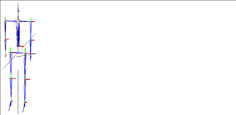
Figure 2.64 A skeleton primitive

To create other skeleton primitives, (CLICK-L) on GeoMenus>File>New Object, then (CLICK-R) on Skeleton. The following types of skeletons can be generated:

Figure 2.65 New skeleton primitives; clockwise from upper left: hips, horse, eight-legged, and six-legged

For more information on using skeletons, see the Skeletal Animation System Reference Guide and the Skeletal Animation System Tutorial.

(CLICK-L) on [Next] to continue...


[N-World Contents] [Book Contents] [Prev] [Next] [Index]

Another fine product from Nichimen documentation!

Copyright © 1996, Nichimen Graphics Corporation. All rights reserved.