[N-World Contents] [Book Contents] [Prev] [Next] [Index]
Working with Bodies (cont.)
Make Displacement
Polyhedra, wires
Saves and names displacements.
Operations in the Displacements section of the GeoMenu let you create, modify, and save displacements for polygons. A displacement is a named, saved state of a polyhedron's vertices or a wire's nodes. What does that mean?
Imagine you were doing a traditional animation with clay models; for each frame, you'd have to repose the skeleton, then shoot a frame. If a character turned his head to the left, you'd have to turn the head slightly for each frame, and shoot it in each new position.
Now imagine that instead of a clay character, you are using a wireframe model in N-Geometry. Using our displacement operations, you could save a pose of the model looking straight ahead as an absolute displacement, rotate the head using one of the rotate commands, then save a pose of the model looking left as a relative displacement.
Each of these displacements can be named and animated from the N-Dynamics animation choreographer as keyframe poses in a script. You might specify that the model start in its original position at frame 1, and that it end looking left (using the relative displacement) in frame 30. When you animated the script, the frames between would be generated automatically, and the model would turn its head to the left.
- Note. You can't add or subtract the number of points on a polygon if you want its displacements to remain valid. This means that operations such as Scale, Twist, and Rotate are valid to create relative displacements, but Collapse and Dissolve are not. For this reason, you should make any changes to your model before making any displacements.
Absolute displacements save information for all vertices on the object; relative displacements save information only for those vertices that have been moved.
There are two types of relative displacements:
The Make Displacement command below shows how each type of displacement is used.
Try the following mini-tutorial to see how displacements work:
1. Make a basic object.
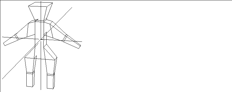
Figure 4.71 Left, object in original position
2. Select Bodies from the sensitivity element menu.
3. (SHIFT-L) on the object, then (CLICK-L) on Make Displacement.
- The following dialog box appears:
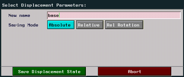
Figure 4.72 Saving an absolute displacement
- Give the object's original position a descriptive name, such as "base." Then choose Absolute (since other displacements are calculated from the object while it's in this "absolute" position).
4. Next, modify or "displace" the object to its target state.
- In this example, we collected the polygons around the man's head and made them larger with the Scale command:
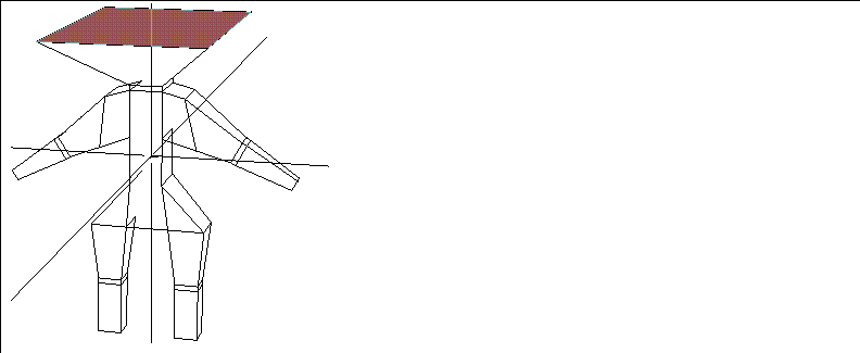
Figure 4.73 Modify the body and save its new position as a relative displacement
5. Select Bodies from the sensitivity element menu.
6. (SHIFT-L) on the object again, then (CLICK-L) on Make Displacement.
7. This time, (CLICK-L) on Relative Displacement.
- Several additional items appear on the menu:
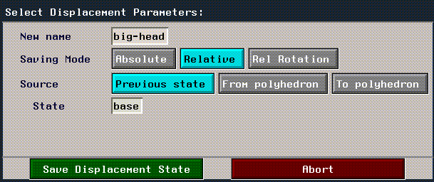
Figure 4.74 Saving a relative displacement
8. Give the relative displacement a descriptive name.
- Again, you can reference saved displacements by name in N-Dynamics.
9. Choose Previous State.
- The current state is based on a previous saved state.
10. Next to State, specify the name of the absolute displacement this pose is based on.
- In this case, we used the name "base" for our absolute displacement.
11. Choose Save Displacement State.
- You've now saved both an absolute and relative displacement state for the object.
12. Test the displacement by selecting the object and (CLICK-M) on the Displace command.
- Initialize the shape to its original state by initializing it to its absolute displacement state.
13. With the object still selected, (CLICK-L) on Displace, and (CLICK-L) on the name of the relative displacement you created earlier.
- Move the mouse left and right to move the object between its original state and its relative displacement.
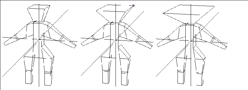
Figure 4.75 Using displacements to change the shape of the man's head
Each of the other options in the Select Displacement Parameters is described below.
Linear vs. rotational displacements
When should you use rotational rather than linear displacements? In a linear displacement, points move from their base position to their target position along a linear path. While this type of animation is easy to calculate, it can cause shearing effects:
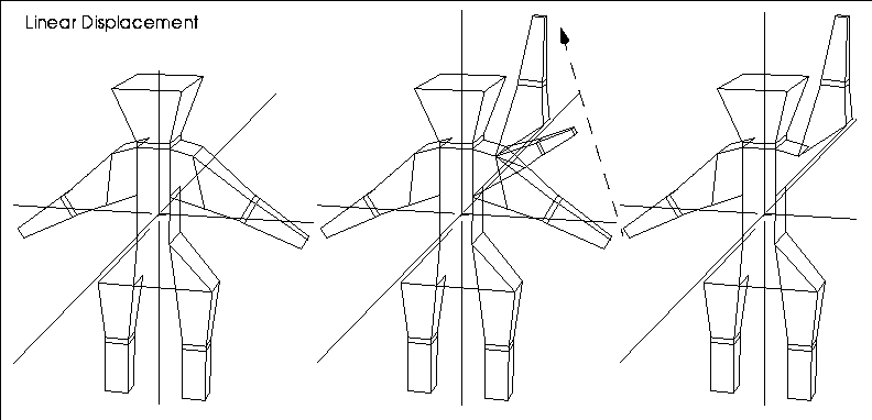
Figure 4.76 When using a linear displacement, points follow a straight path to their target state, which can cause shearing or distortion
Linear displacements make sense if you're performing operations on an object that wouldn't cause points to be moved through other points (such as scaling or moving).
In a rotational displacement, points move rotationally around a selected axis:
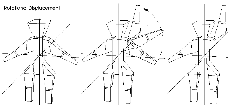
Figure 4.77 Left, displacing using a rotational displacement lets you select an axis which the displaced vertices rotate around
Choose rotational displacements if the operation you want the displacement to follow a curved rather than straight path. You specify the rotation axis that the displaced points are to rotate around when defining the relative rotational displacement (notice the addition of the Axis menu item):
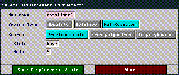
Figure 4.78 Saving a rotational displacement
To make a rotational displacement:
1. Set the item to base shape.
2. Save an absolute displacement for the object.
3. Displace the shape to its target state.
4. (CLICK-L) on Make Displacement.
5. Choose Rel Rotation for the type of displacement.
6. (CLICK-L) on Axis.
- The menu that appears lets you choose an axis that the points should rotate around (typically a point on the object itself). In the example above, we selected the Select a segment option and chose the segment on the arm that the rotation occurs around:
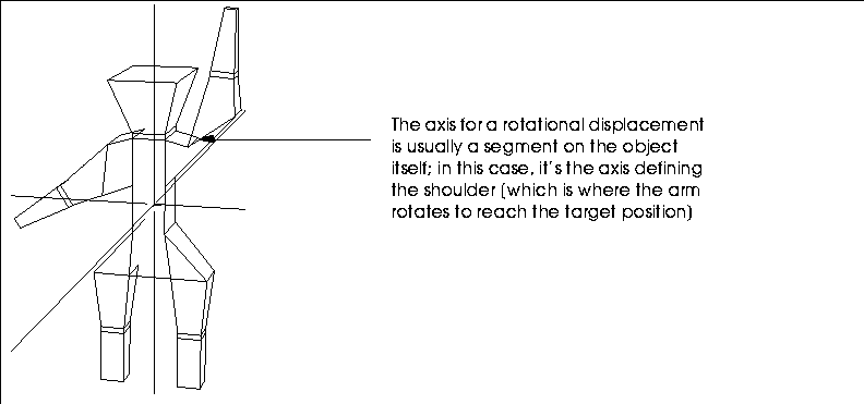
Figure 4.79 Selecting an axis for a rotational displacement
Both linear and rotational displacements can be animated using the Displace command, described below.
Make Frozen Mapper
Any body
Fixes the relationship of the specified mapper to the surface of the object. To do this, you need to capture the mapper and the position of the vertices at a certain point in time and save those positions for reference during rendering.
This is called "applying a dynamic mapper" and produces a frozen mapper. The resulting frozen mapper is a copy of the dynamic mapper, saved with the positions of the object's vertices and the mapper's transformation at the time it was created.
You typically apply a mapper to an object that changes shape (deforms) over the course of an animation.
When you animate an object with a frozen mapper, the map image always remains in the same position on the surface of the object. Because a frozen mapper represents a fixed mapping relationship, no visible mapper object exists for frozen mappers, nor can their transformations be animated.
Creating and applying mappers is discussed in detail in the N-Geometry Tutorial.
Make Part Frozen Mapper
Faces, bodies
Applies a mapper created in N-Geometry to a selected face part.
The creation and application of mappers is discussed in detail in the N-Geometry Tutorial.
Make Patch Body
Polyhedron
Makes a patch-body for the currently selected object. A patch body has the same number of vertices, edges, and faces as the original object; however, all edges are smoothed in the "patched" copy. The effect is particularly visible if you turn shading on for the patch body object. Some renderers require patch bodies for rendering purposes.
To create a patch body:
1. Create an object.
2. (SHIFT-L) on the object.
3. (CLICK-L) on Make Patch Body.
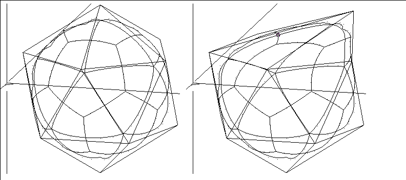
Figure 4.80 Left, original object with patchified body; right, after moving point on original object
After you (CLICK-L) on Make Patch Body, a menu pops up to give the new patched body a name.
To change the shape of the patchified body, change the shape of the original polygon body; in Figure 4.80, we moved a point on the original, or "control" icosahedron to deform the patch body.
Make Spline
Wires
Creates a splined wire from a control wire. The splined wire is actually a regular wire whose nodes lie on a b-spline curve that uses the control wire's nodes as control points.
To create a splined wire:
1. (SHIFT-L) on a previously encoded wire.
- The following menu appears:
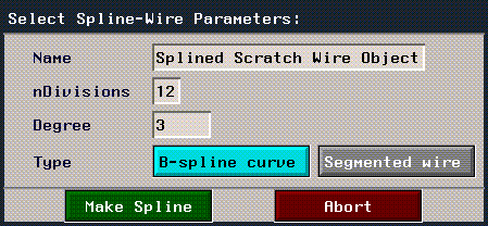
Figure 4.81 Selecting spline-wire parameters
- Note. Using a value for Degree higher than the number of segments in the control wire produces no additional changes.
Figure 4.82 Left, B-spline curve encoded from control wire; right, segmented wire
- Note. Splined wires cannot be made from wires that contain arcs.
Make Splined Surface
Rectangular mesh
This feature lets you create a new polyhedron approximating a B-spline surface of arbitrary degree, using the rectangular mesh nodes as control points.
To make a splined surface:
1. Create a rectangular mesh.
- Create the mesh from the GeoMenus>File>New Object>Grid menu.
2. Pull out several points from the rectangular mesh by performing an Axis Move along the Y axis.

Figure 4.83 The rectangular mesh
3. (SHIFT-L) on the mesh.
4. (CLICK-L) on make splined Surface.
- The following menu appears:
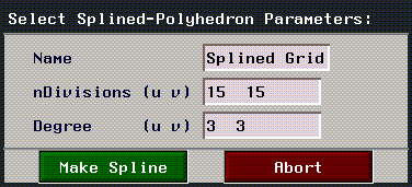
Figure 4.84 Menu for creating splined surface from rectangular mesh
5. (CLICK-L) on the Make Spline button.
- The splined surface appears under the original rectangular mesh:
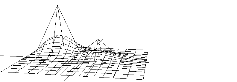
Figure 4.85 The rectangular mesh with the generated spline surface beneath it
6. To change the shape of the generated spline surface, move points on the original rectangular mesh:
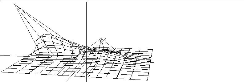
Figure 4.86 The rectangular mesh with the generated spline surface beneath it
Materials
Assigns or removes materials from the selected body, or invokes the Attributes Editor, which is used to edit materials.
Materials define how a body will look when it is rendered; you can specify things like a color, opacity, and surface texture for the material used to render the object.
For a complete description of attributes and how they are assigned, refer to the Attributes Editor User Guide.
Mirror
Polyhedra
Duplicates the geometry of a polyhedron by copying it around a selected face. The result is the original object with twice the geometric complexity (no discrete polyhedra is created). Copy, mirrored resembles the Mirror command, except that the mirrored polyhedron becomes a new object.
Figure 4.87 Mirrored icosahedron
Move
Edges, faces, polyhedra, vertices
Moves the selected element in one of three ways:
When you move a face, the other faces move (stretch or shrink) to maintain continuity. This is also true with edges and vertices; when they are moved, the polyhedron changes as necessary.
- Note. It is very easy to generate non-planar faces with the move operation. By moving a vertex at random, adjacent faces can easily become non-planar. If you intend to render an object and you know how you want the object to look, you can use Cut to divide the object into triangles. If you do not cut faces, most renderers triangularize non-planar faces automatically, which might cause the object to be rendered in a manner you did not intend.

Figure 4.88 Cube before and after point move
Move Texture
Vertices
Modifies the UV coordinates of a frozen mapper, effectively "sliding" the area of the texture map around the selected vertex. Use this command to fine tune the position of a map in relation to a body, i.e., to align a feature on a map with a feature on an object.
- Note. You can only use Move Texture on a frozen mapper.
To move the texture of a frozen mapper:
1. Create a frozen mapper.
- See the section "Make Frozen Mapper," on page 4-57 for details on how to create a frozen mapper.
2. Apply a material to the body and make sure the texture map is applied to the body through the frozen mapper.
3. (CLICK-L) on points on the element sensitivity menu.
4. (SHIFT-L) on a vertex on the body that is close to where you want to slide the map.
- For example, you may want to align the lines in a map with the edges of an object:
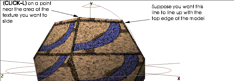
Figure 4.89 Selecting a point on the body near where you want slide the texture
5. (CLICK-L) on Move Texture.
- A list of mappers associated with the body is displayed. (CLICK-L) on the mapper whose UVs you want to change.

Figure 4.90 Select the frozen mapper you want to adjust
6. Move the mouse to slide the texture interactively.
- You can repeat this process for any number of points on the body until your texture is properly aligned:
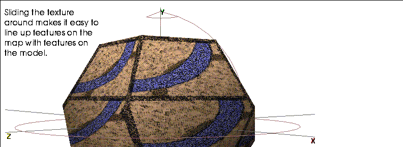
Figure 4.91 After sliding the texture around each of the point on top of the object
Multiple Extrude
Faces, collections of faces
Multiple Extrude lets you perform multiple operations on a face or collection of faces at one time. In addition to the basic extrusion of a face, you can move, scale, rotate, twist, and circularize the face as it is extruded from the original body. In addition, the extrusion can be given a "domed" appearance. This feature is great for pulling out horns, antennae, claws, etc. on creatures, or any non-uniform extrusion from a body.
- Note. If you want to extrude all the faces on an object, you must select the faces; a quick way to do this is to select the object, then (CLICK-R) on Select Elements to select all of its faces.
(SHIFT-L) on the element you want to extrude and select Multiple Extrude. The following menu similar to the one shown in Figure 4.92 appears:
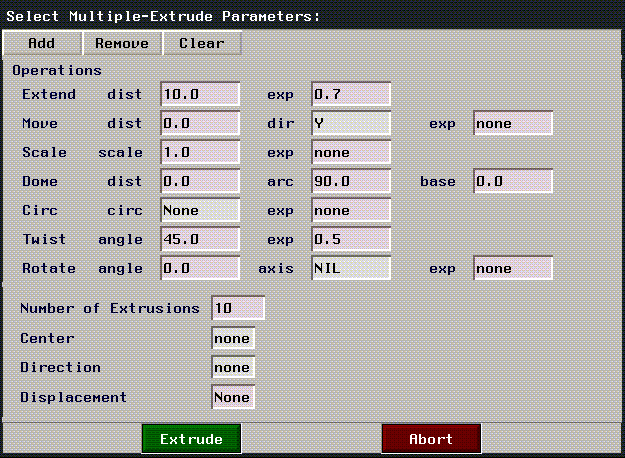
Figure 4.92 Multiple extrude menu (showing all operations)
The menu shown in Figure 4.92 displays all the possible extrusion operations that can be performed on an element. When the menu first appears, no operations are displayed. To add an extrusion operation (that will be performed on the selected element) (CLICK-L) on the Add button. The following menu appears:
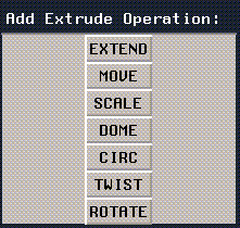
Figure 4.93 Multiple extrude operations
(CLICK-L) on the type of extrusion you want to perform. Because you can also specify a number of times that the element is extruded, you can also specify an exponent value that determines the length of each extrusion.
Each time you click on an extrusion operation, it is added to the list in the menu shown in Figure 4.92. For each extrusion operation, enter the parameters required for that operation.
- Note. The effect of Inner and Outer is more apparent when there is a greater disparity between the outermost and innermost points on the face being circularized.

Figure 4.94 Measuring the radius for a circularized extensions. Left, inner radius; right, outer radius
Figure 4.95 Multiple extrude operations: extrude only, extrude plus move, scale, dome, circle, twist, and rotate
Experiment with different combinations to see the unique effects you can create. A complete section can be found on the Multiple Extrude command in the N-Geometry Tutorial.
Part Materials
Faces, collections of faces, bodies
Lets you assign or remove attributes from the part to which the selected element belongs. After selecting the element:
For a complete description of attributes and how they are assigned to parts, refer to the Attributes Editor User's Guide.
Parts
Edges, faces, rectangular mesh, polyhedra
Select from a list of parts. Choosing a part selects all the elements of that part so that you can carry out the same operation on all elements of that part at the same time.
Plane Cut
Faces, polyhedra
Cut both faces and polyhedra with an intersecting plane. You can also truncate a polyhedron by cutting it with a plane, discarding one half or the other, and then sealing the resulting openings with one or more faces.
To plane cut or truncate, you must first define a plane by specifying a direction normal to the plane and the location of a reference point through which the plane will pass.
Figure 4.96 A cube with a plane cut using the normal of the Y face
Figure 4.97 Truncated man, keeping the positive, using the normal of the Y face
Figure 4.98 Specifying an area for plane cuts to take place
- Note. Most users find it easiest to select the Lower Bound and Upper Bound using the Point Along Element method from the menu that appears when you (CLICK-L) on those text edit boxes.

Figure 4.99 Element with multiple plane cuts between specified points (normal to the X plane)
Position
Most element types
Moves an element by aligning its midpoint with a point in global space (usually a vertex on the same or another object). The object is moved locally, preserving its current orientation and scale, so that the selected feature coincides with the selected point.
Figure 4.100 Two cubes

Figure 4.101 Repositioning a point, edge, or face

Figure 4.102 Repositioning a polyhedra
Figure 4.103 Menu to position an object
Position Highlight
Point, infinite, and spot lights
Specify a location on a surface where, from the current camera position, the light's highlight will fall. This operation performs the function by adjusting the light's position (for point lights) or direction (for infinite lights).
- Note. Shadows are only created by a light if the renderer used to create the image supports shadows and the attributes of the illuminated objects in the scene must specify a light group that includes this light.
Because shades objects share the same lights with N-Render and use the same gamma correction if N-Render is loaded into the environment, you can closely approximate what an object would look like if it were rendered with Lambert shading. See the section "Shading," on page 6-7.
Randomize
Polyhedra
Adds a degree of noise to a polyhedron.
Figure 4.104 Sphere with vertices randomized along vertex normals
Replace with Arc
Wire segments
You can replace segments of wires with arcs. Simply click on Replace with Arc to substitute an arc for a selected segment. Once you replace a segment with an arc, you can replace the arc with a segment again by using Replace with Segment.
This is useful if you are want to perform operations that can only be performed on one type of element.
[N-World Contents] [Book Contents] [Prev] [Next] [Index]
 Another fine product from Nichimen documentation!
Copyright © 1996, Nichimen Graphics Corporation. All rights
reserved.


 Another fine product from Nichimen documentation!