[N-World Contents] [Book Contents] [Prev] [Next] [Index]
Working With Bodies (cont.)
Dehole
Faces with holes
Removes holes from faces. Because N-Geometry is based on a winged-edge database design, any segment must know about its immediate neighbors. Some operations, however, can temporarily create holes in faces that must be eliminated before some renderers can render the object.
See the section "Inset," on page 4-42 for a description of how the Dehole command is typically used.
Derez
Bodies, collections of faces
Simplifies the topology of the object or group of faces by dissolving edges (while retaining the object's original shape). The resolution can be reduced by various methods, all under the user's control.
To Derez an object:
1. (SHIFT-L) on the object or group of faces.
- The following menu appears:
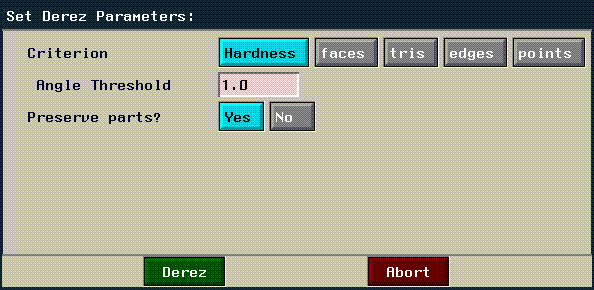
Figure 4.35 Derez menu
Each of the options attempts to derez the object using different methods:
Describe
Any element
Prints a description of a selected element in the UNIX shell window.
Figure 4.36 Description of face on a polyhedron
Displace
Polyhedra, wires
Displace lets you not only deform vertices and nodes within the defined states of the displacements, but to extend beyond the initial state of any displacement.
You name and save displacements through the menu item Make Displacement. Displacements are especially useful for animating non-rigid motions of a polyhedron and are commonly used in conjunction with operations that influence an entire area (particularly useful for facial expressions).
Displacements can be animated through N-Dynamics.
Figure 4.37 Displacing an object numerically
- Choose a target displacement state, then enter how far toward that state you want to displace the object:

Figure 4.38 Displacing an object numerically
- Use a value of 0.5 to go halfway to the saved state; use a value of 1.0 to go completely to the saved state.
- Note. You can specify values above 1.0 if you want to displace the object beyond the displaced state.
Figure 4.39 Managing displacements
Using Displace to Build Gestures
If you have saved several displacements, you can combine them and save those combinations as "gestures." Gestures are no more than displacements based on other displacements.
Using the same basic man figure we described in the sections "Make Displacement," on page 4-50 and "Displace," on page 4-27, we could combine several saved relative displacements into a gesture. To make a gesture, you must have saved an absolute base displacement for the object and at least two relative displacements for the object.
1. (SHIFT-L) on the object.
2. (CLICK-R) on Displace.
3. Choose Displace Multiple.
- A menu similar to that shown below appears:
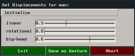
Figure 4.40 Defining a gesture
4. Move the sliders to apply displacements to the object.
5. When the object looks "right," (CLICK-L) on Save as Gesture.
- Note. Gestures are particularly useful when defining facial expressions. You can use relative displacements to define states for different parts of the face (e.g., open-eyes, open-mouth, big-smile), then combine those displacements into more complex combinations (such as laugh or scream).
You can then animate between those saved states in N-Dynamics.
Dissolve
Edges, collections of edges
Eliminates the selected edges and turns the adjoining faces into one face. If the two faces do not lie on a common plane, this command creates a nonplanar polygon.

Figure 4.41 Dissolving an edge
This is an effective technique to reduce the number of polygons on a model being developerd for a game console.
Edge Subdivide
Faces, collections of faces, polyhedra
Cuts one face (or faces) of a polyhedron into many faces.
Figure 4.42 Left, face subdivided into quadrilaterals; right, face subdivided into
triangles
Evert
Polyhedra
Turns a polyhedron inside out, by flipping its normals.
This feature is extremely useful if you want to render both the inside and outside of a given object; suppose, for example, that you were creating a game that featured a single-object arena. If rendering the object from the outside, you'd want the normals facing out; however, when you moved inside the arena, you'd want to use Evert to flip the normals (so that you could render the inside of the object).
Extrude
Edges, faces, vertices, element collections
Extrude pulls the selected element away from the main polyhedron, maintaining the surface integrity of the body.
Depending on which type of element you are extruding, additional faces may be created:
Once you've begun extruding an element, (CLICK-R) to abandon the change, leaving the element in its original position but with new neighboring faces.

Figure 4.43 Cube with vertex, edge, and face extruded
You can extrude an entire collection of elements to avoid repeating the same extrude operation on a element by element basis; for example, you might collect all the faces around a cube, then (CLICK-L) on Extrude to extrude all the selected faces equally:
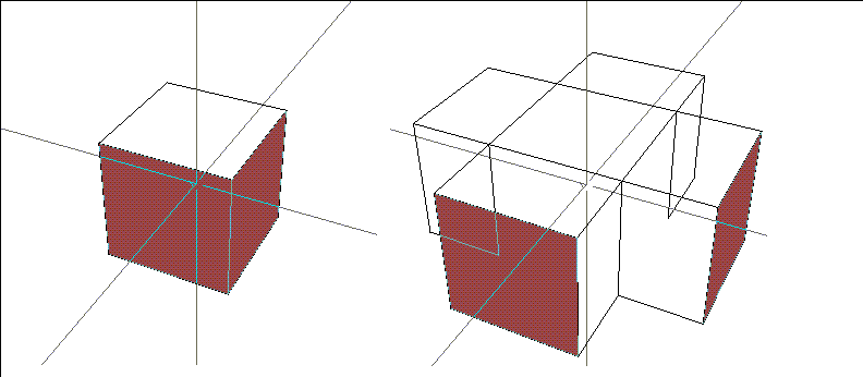
Figure 4.44 Left, collection of faces; right, faces extruded in one operation along their normals
Extrude Region
Collection of faces
Extrudes a collection of faces along a selected normal:
To extrude a collection of faces as a region:
1. Collect the faces you wish to extrude.
2. (SHIFT-L) on the collection, then (CLICK-L) on Extrude Region.
- Move the mouse left and right to extrude the region:
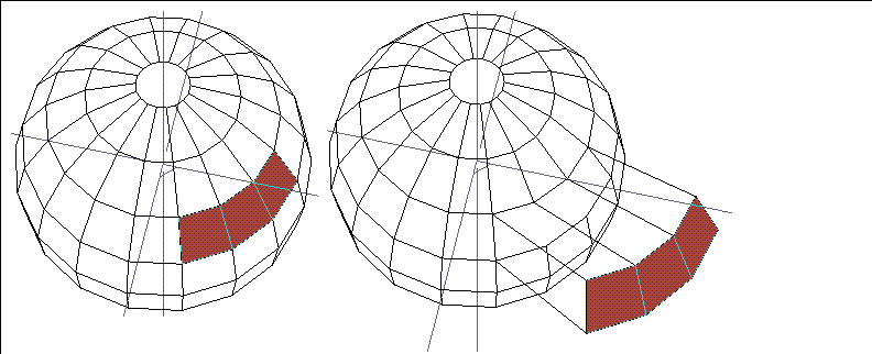
Figure 4.45 Left, collected faces: right, faces extruded as a region
Extrude Region differs from Extrude in that the collected faces are moved as a group (along the average normal of each contiguous collection) rather than along their individual normals. For example, if the same faces selected in Figure 4.45 were extruded, they would follow their own normals:
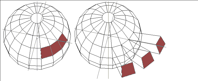
Figure 4.46 Same faces, moved out with Extrude rather than Extrude Region
Falloff Angle
Spotlights
Changes the area where light falloff begins around the edges of this light's spot pattern. This operation is interactive:

Figure 4.47 Left, original light; right, same light with modified falloff angle
Light within the inner portion of the spot pattern strikes an object at full intensity; falloff begins between the solid and dotted line in the spot pattern.
Flatten
Edges, faces, vertices
Makes the selected element lie on the specified plane. This can be used, for example, to align all the points on a face in one plane.
To flatten an element or group of elements:
1. Collect the elements you want to flatten.
2. (SHIFT-L) on the collection, then (CLICK-L) on Flatten.
3. Select the element you want to align the collected elements with.
4. Select the axis along which you want to align the collected elements.
For example, you might align a face on the mountain below on the Y axis by selecting a point on the edge of the grid and specifying the Y axis:

Figure 4.48 Left, original grid; right, selected elements flattened on the global Y axis
Flip
Edges, bones
Recreates two faces by dissolving the selected edge and reconnecting it to points either clockwise or counterclockwise from the current edge.
Flip is useful if you have loaded a damaged object and need to flip only a few segments to correct it.
Figure 4.49 Cylinder with one edge flipped (counterclockwise)
Flip can also change the orientation of a bone in relationship to the root node. This can be particularly useful if you want to change the location of the root node to a neighboring segment; select the neighboring segment then choose Flip to change the location of the root node.
Flip Path
Arc
When you create a contour that contains an arc, you cut the arc out of a circle. (See Figure 4.50) Although both arcs are left after subdividing the circle, the default treatment is to use the smaller arc as part of the path. If you later make a wire from the contour, you can use Flip Path to make the larger arc part of the wire. (See Figure 4.51.)
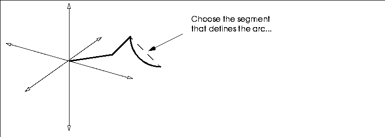
Figure 4.50 Sketch of arc with wire
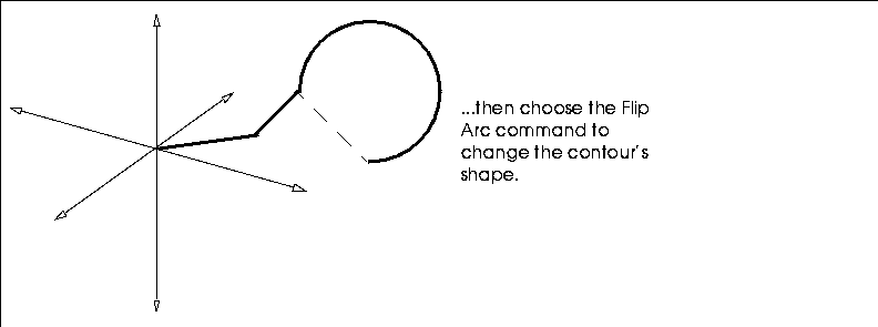
Figure 4.51 Top, wire created from sketch; bottom, after path of arc was flipped
Fractalize
Face collections, polyhedra
Fractalizing an object gives it a bumpy, random surface. Randomness can be created by either cutting edges or beveling them.
Fractalize subdivides faces by cutting edges where points are randomly placed. The amount of displacement is specified as a ratio of edge length for each xyz coordinate. Although these values are usually the same (they default to .2), you can emphasize or deemphasize the bumpiness along any axis by raising or lowering that value.
Figure 4.52 Left, original icosahedron; middle, fractalized once; right, three times
Figure 4.53 Fractal menu
- The menu lets you specify both initial and final random factors; N-Geometry then interpolates between them. This lets you vary the randomness based on the degree of fractalization. Although this capability undermines the self-similar properties of a true fractal, it is useful for various effects.
- The menu also lets you specify the quantity of iterations to be performed. Each iteration approximately triples the number of edges and quadruples the number of faces.
Figure 4.54 Icosahedron fractalized by beveling edges
Free Rotate
Any element
Rotates the selected body independently around the X, Y, or Z axes.
You can specify whether the X, Y, and Z axes are local, global, or for some other predefined object by using the appropriate mouse click:
Free Rotate Aimed
Eyepoint of spotlights
Rotates the eyepoint of a spot light independently around the X, Y, and Z directions while keeping the aimpoint of the light fixed.
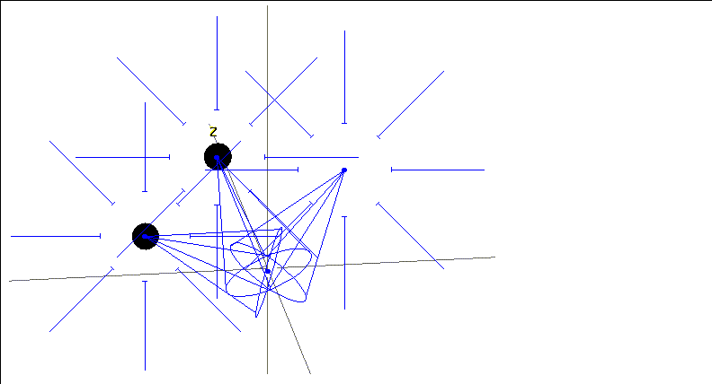
Figure 4.55 Free Rotate Aimed of a spot light's aimpoint
You can specify whether the X, Y, and Z axes are local, global, or for some other predefined object by using the appropriate mouse click:
Free Scale
Any body
Lets you scale a body around the X, Y, and Z axes.
You can specify whether the X, Y, and Z axes are for the object's center, an arbitrary vertex, or some other vertex selected from a menu:
Grow
Polyhedra
Changes the object by moving the edges of the polyhedron inward or outward along their normals.
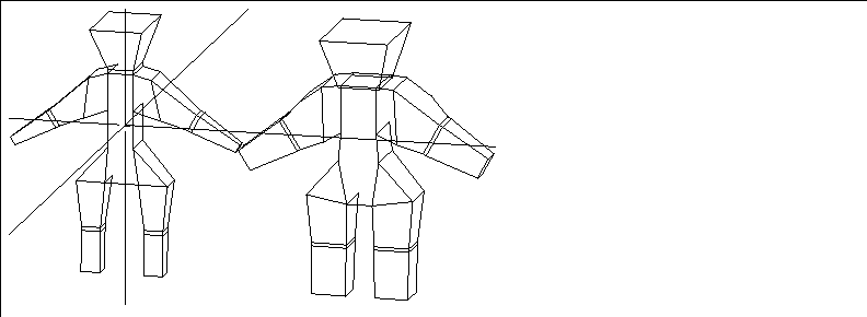
Figure 4.56 Left, original man; right, man with grown faces
Hue
Ambient, point, infinite, and spot lights
Interactively adjust the color component of a light. For example, blue and red are different hues.
To adjust the hue of a light interactively:
1. (CLICK-L) on points on the element sensitivity menu.
2. (SHIFT-L) on the light, then (CLICK-L) on Hue.
- Move the mouse left and right to adjust the hue of the light.
As you move the mouse, both the body and its emitted light update interactively. For more information on lights, see the sections "Brightness," on page 4-9, and "Saturation," on page 4-79.
- Note. You can also adjust the hue of the light using the Attributes Editor, or use (CTRL-L) on Hue to set the light value numerically.
Illegal Faces
Bodies
Highlights faces on the selected body that are non-triangles, non-quads, or non-flat, depending on which mouse click is selected:
Figure 4.57 Finding illegal faces
Finding illegal faces is an iterative process; find the faces, then use commands like Cut to make them legal, use Illegal Faces again, and repeat until your model consists of only the face types you want to send to your target platform.
Inset
Faces, face collections, polyhedra
Figure 4.58 Cube with one face inset the default amount
1. Make sure both faces are perpendicular.
- For this operation, let's use a sample cube and a lamina:

Figure 4.59 Cube and lamina (to be used for inset)
- N-Geometry does not position the face for you when you use this feature. Ideally, you should put the face to be used as an inset on the same plane as the face you are embedding it into.
2. Make sure the face to be used as an inset is visible.
- You cannot use a second face from the same polyhedron as the selected face.
3. (SHIFT-L) on the lamina.
4. (CLICK-L) on Flatten.
5. (CLICK-R) on "Z".
- While you choose Z in this case, you'll normally choose whatever axis the two faces are aligned along.
6. Choose which Z axis to use.
- In this case, let's choose the cube's Z axis.
7. Choose a point on the front face of the cube.
- This aligns the two faces in one plane.

Figure 4.60 Lamina flattened onto front face of cube
8. (SHIFT-L) on the face you want to embed the shape onto.
- In this case, the front face of the cube.
9. (CLICK-M) on Inset.
- The Modify Element menu goes away and your cursor reappears.
10. (CLICK-L) or (CLICK-M) on the lamina's face.
- N-Geometry uses the perimeter of the second face to create another face within the first face. If you select the original face, you can see the created "hole."

Figure 4.61 Select front face of cube after lamina's face has been inset
11. (SHIFT-L) on the face into which the lamina was inset and choose the Cut command.
12. (SHIFT-L) on the original face and choose the Dehole command.
- For an object to be "legal" it cannot have holes on a face. The resulting face should look something like this:

Figure 4.62 Deholed face after lamina has been inset
Figure 4.63 Cube with lamina aligned with front and back planes
1. With Faces selected in the element sensitivity menu, select the two planes you want to inset the lamina into.
- In this case, (CLICK-L) on the front and back faces, then (CLICK-R) to finish the collection.
2. (SHIFT-L) to bring up the modify menu.
3. (CLICK-R) on Inset.
4. (CLICK-L) on the Lamina you want to inset.
5. Select the axis along which you want to project the lamina.
- In this case, it's the Z axis. The faces are projected onto the collected faces:

Figure 4.64 Lamina projected onto front and back planes
6. With the faces still selected, (SHIFT-L) to bring up the modify body menu again, then (CLICK-L) on the Dehole operation (as described above)

Figure 4.65 Lamina inset onto parallel planes, then bridged
Interp Smooth
Faces, polyhedra
Subdivides faces and polyhedra, with an effect similar to that of Edge Subdivide. This operation positions the new vertices in such a way that the angle between adjacent faces is minimized, leaving the existing vertices in place. Several iterations of this function produce a smooth surface that interpolates all the points of the original set of faces.
Figure 4.66 Octahedron smoothed
Figure 4.67 Octahedron smoothed
Figure 4.68 Selecting smoothing parameters
Lift from Edge
Faces
Moves a face by pinning a selected edge and pulling out the face using that edge as a "hinge."
To lift a face:
1. Select the face you want to lift.
2. Select the Lift from Edge command.
- You are put into segment sensitivity mode.
3. Choose the segment you want to pin the face with.
In all three examples below, we did a (SHIFT-L) on the top face of the cube and selected the leftmost segment of the top face when prompted; then the top left segment of the face was selected as the constraining edge.

Figure 4.69 Left, (CLICK-L) on Lift from Edge; middle, (CLICK-M), right, (CLICK-R)
While lifting edge of a face, (CLICK-R) to abandon the motion, leaving the element with new neighboring faces but in its original position.
Lift from Vertex
Faces
Moves a face by pinning one of its vertices and pulling it out, with the pinned vertex limiting how the "lifted" face can be moved.
To lift a face from a vertex:
1. Select the face you want to lift.
2. Select the Lift from Vertex command.
- You are put into point sensitivity mode.
3. Choose the point you want to pin the face with.
In all three examples below, we did a (SHIFT-L) on the top face of the cube and selected the leftmost segment of the top face when prompted; then the front left point of the face was selected as the constraining vertex.

Figure 4.70 Left, (CLICK-L) on Lift from Vertex; middle, (CLICK-M), right, (CLICK-R)
While lifting a face, (CLICK-R) to abandon the motion, leaving the element with new neighboring faces but in its original position.
(CLICK-L) on [Next] to continue...
[N-World Contents] [Book Contents] [Prev] [Next] [Index]
 Another fine product from Nichimen documentation!
Copyright © 1996, Nichimen Graphics Corporation. All rights
reserved.


 Another fine product from Nichimen documentation!