In this chapter, we'll describe some techniques for adding detail to selected areas of an object.
In this Chapter
We'll describe some of the commands that you typically use to add geometry to an object, including:
In this chapter, we'll describe some techniques for adding detail to selected areas of an object.

We'll describe some of the commands that you typically use to add geometry to an object, including:
In this Chapter
In general, you need to add geometry in the following cases:
The Cut command has two basic uses:
Cut
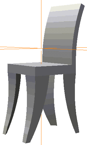
Building a Chair
When do you need to cut a face?
2. (SHIFT-L) on the bottom face of the cube, then (CLICK-M) on Select Elements.
4. (SHIFT-L) on the bottom face, then (CLICK-L) on Cut.
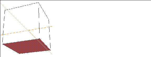
5. Move the cursor over the selected face.
7. Now, (CLICK-L) on the vertex just on the other side of the corner.
Figure 11.3 Select the face you want to cut8. Now, repeat the Cut operation for the other corners.
Figure 11.4 Make three more cuts like the first
Now, move the camera so that you're looking at the top of the cube.
9. (SHIFT-L) on the top face, then (CLICK-L) on Axis Move.
Figure 11.5 Axis Move the top of the cube10. (SHIFT-L) on one of the segments along the side of the cushion, then (CLICK-R) on Cut.
11. Make a similar cut on the other side of the cushion.
To straighten out this cut, let's use the Flatten command.
14. (CLICK-L) on Z for the axis to Flatten along.
15. (CLICK-L) on the corresponding vertex on the other side of the cushion.
Figure 11.8 Straightening the cut
Now we can use the Multiple Extrude operation to pull out the back and legs of our chair.
16. (SHIFT-L) on face you created with the cut operation.

17. (CLICK-L) on Multiple Extrude.
23. Move the camera back so that it's pointed at the bottom of the chair again.
24. Collect the two triangular faces at the back of the chair bottom.

25. (CLICK-L) on Multiple Extrude.
29. You can use the same parameters you used to pull out the back legs, with one exception:
30. Now, collect the four feet on the bottom of the chair legs.
31. (SHIFT-L) on the collection and (CLICK-L) on Flatten.
32. Choose the lowest point on one of the chair legs.
33. (CLICK-L) on Y for the axis to flatten along.
Figure 11.14 Flattened feet34. (CLICK-L) on GeoMenus>Object Display>Shading>Cube to shade the object:
The Edge Subdivide command adds geometry by cutting a face from the midpoint of each edge to the face's midpoint.
Edge Subdivide
1. (CLICK-L) on GeoMenus>File>New Object.
3. (CLICK-L) on the Make Grid button.
Figure 11.16 Create a grid
Even if you didn't create any mountains, continue on with these steps:
5. Collect several faces on the grid.

6. (SHIFT-L) on the collection, then (CLICK-L) on Edge Subdivide.
7. Collect several of the smaller faces and Edge Subdivide them.
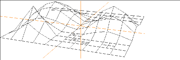
8. Now, use the Extrude and Multiple Extrude tools to pull up the faces into a small city.
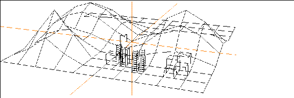
Of course, Edge Subdivide will work on any face with any number of sides:
9. Create a tetrahedron, a cube, and a dodecahedron.
10. Select objects in the element sensitivity menu, then use Axis Move>X to spread the objects out.
11. Collect the faces shown below:

12. (SHIFT-L) on the collection, then (CLICK-L) on Edge Subdivide.
Figure 11.23 Faces are inscribed from the midpoint of each edge to the face
Vertex Subdivide also adds geometry by cutting a face. However, instead of cutting the face from the midpoint of each edge, a segment is cut from each vertex to the face's midpoint.
Vertex Subdivide
1. Create a tetrahedron, a cube, and an dodecahedron.
2. Select objects in the element sensitivity menu, then use Axis Move>X to spread the objects out.
3. Collect the faces shown below:
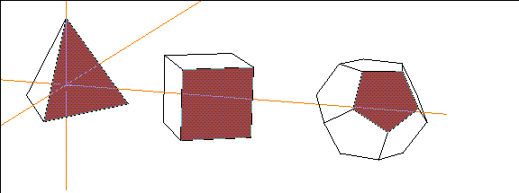
4. (SHIFT-L) on the collection, then (CLICK-L) on Vertex Subdivide.
Figure 11.25 Faces are inscribed from each vertex to the face midpoint
Vertex subdivide is handy if you want to pull out a "spike" from a face:
5. (SHIFT-L) on the vertex on the face midpoint of one of the objects, then (CLICK-L) on Axis Move:
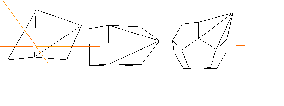
Beveling an edge or vertex replaces that element with a face aligned with the vertex or edge's normal. You can think of a Bevel operation as slicing off a corner or edge of an object.
Bevel
2. (SHIFT-L) on one a vertex on one of the corners, then (CLICK-L) on Bevel.
Figure 11.27 Bevel parameters3. (CLICK-L) on the Bevel button.

The resulting face can then be extruded, scaled, and modified.
Beveling a Segment
Beveling a segment affects only that edge:
5. (SHIFT-L) on one an edge of the cube, then (CLICK-L) on Bevel.
If you bevel an edge in the middle of a flat surface, you get the following result:
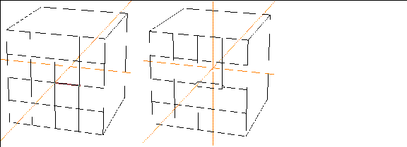
Beveling a Body
When you bevel an entire body, it has the effect of "sanding all the sharp edges down;" both edges and points are beveled:
7. (SHIFT-L) on the cube, then (CLICK-L) on Bevel.
The Smooth function is one of N-Geometry's most powerful features.
Smooth
Smoothing an Entire Object
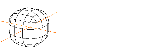
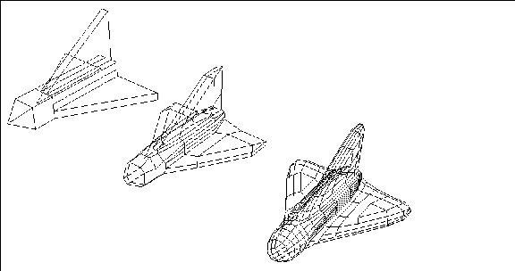
Working even with a simple object like a cube lets you see how the smooth operation adds geometry.
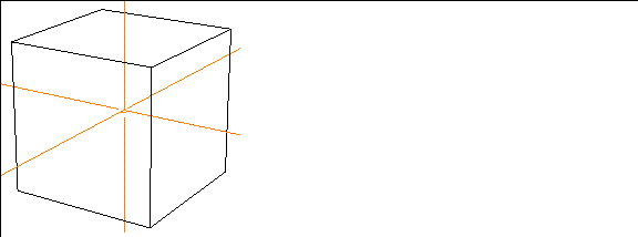
2. (SHIFT-L) on the cube, then (CLICK-L) on Smooth.
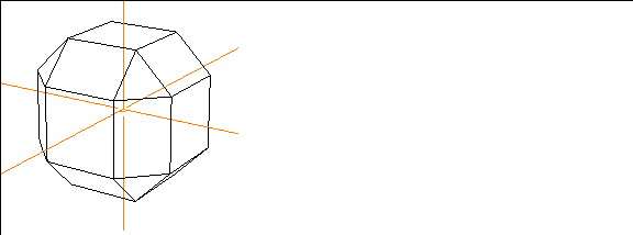
3. (SHIFT-L) on the cube again, then (CLICK-L) on Smooth again.
Smoothing Part of an Object
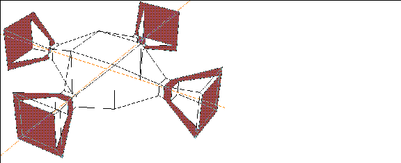
If you only need to add detail to part of an object, then only smooth that part!
Suppose you'd drawn a loudspeaker system and wanted to smooth the horn portions:
1. Collect the faces on the area(s) you want to smooth.
Smoothing Tips
When you're building a model in N-Geometry, it's a good thing to know if you eventually plan to smooth the model or not.
Suppose that in the previous example (our loudspeaker) that we had created the object like this:
3. Select the edge loops closest to the ends (but not the end loop).
4. Scale the collected segments.
If we were to smooth this entire object, we'd get some results that you might not expect:
6. Extrude the faces on each side once.
7. Now, make another very narrow extrusion so that your object looks like this:
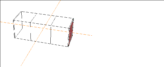
9. Make a final very narrow extrusion, so that your object looks like this:

10. Select the segments in all four edge loops that make the final "joint."

11. (SHIFT-L) on the collection, then (CLICK-L) on Scale to scale down the segments:

12. Now, (SHIFT-L) on the body and (CLICK-L) on Smooth.
Figure 11.46 Smoothed objectCompare this result with the diagram in Figure 11.41; note that the scaled "joints" are maintained, and the object ends are kept closer to their original scale.
You've learned some additional techniques for adding geometry to local areas of an N-Geometry object. The cut, bevel, edge subdivide, vertex subdivide, and smooth commands can all be used to add geometry to parts of an object, or to change the appearance and topology of the entire object.
Congratulations!
 Another fine product from Nichimen documentation!
Copyright © 1996, Nichimen Graphics Corporation. All rights reserved.