In this chapter we'll review some basic techniques for collecting elements on an object and for working with parts.
In this Chapter
You'll learn about:
In this chapter we'll review some basic techniques for collecting elements on an object and for working with parts.

You'll learn about:
In this Chapter
Up until now, whenever you've needed to select elements on which you wanted to perform an operation, you needed to select each element individually while in collect mode. While this is often the mode you'll want to work in, there are some other options.
Selecting Elements
Select Elements
The Select Elements command is context sensitive-it works differently depending on whether you have a body, face, segment, or point selected.
Bodies
With a body selected, the Select Elements command lets you select the points, segments, or faces on that object, depending on whether you (CLICK-L), (CLICK-M) or (CLICK-R).
2. (CLICK-L) on bodies on the element sensitivity menu.
3. (SHIFT-L) on the cube, then (CLICK-L) on Select Elements.
4. (CLICK-L) on bodies on the element sensitivity menu again.
6. This time, (CLICK-M) on Select Elements.
7. (CLICK-L) on bodies on the element sensitivity menu again.
9. This time, (CLICK-R) on Select Elements.
Faces
With a face selected, Select Elements works like this:
10. Select a single face on the cube.
12. (CLICK-L) on select elements.
13. (SHIFT-L) on a single face on the cube again.
14. (CLICK-M) on select elements.
15. (SHIFT-L) on a single face on the cube again.
16. (CLICK-R) on select elements.
Selecting Neighbors
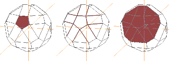
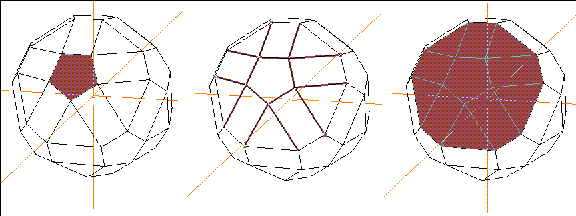
Selecting neighboring elements lets you gather elements of the specified type that are adjacent to the currently selected element. To see this example clearly, let's use a different object.
17. Create an icosahedron (GeoMenus>File>New Object>Icosahedron).
18. (SHIFT-L) on the object, then (CLICK-L) on Smooth.
19. (SHIFT-L) on a single face on the icosahedron.
20. (SHIFT-L) on select elements.
Segments and Points
With segments and points, you can use the same techniques described above for faces to collect other element types. Here's a summary of what get's selected with the Select Element command.
Select Edge Loop
The Select Edge Loop command tries to collect a loop of segments around the surface of an object. Try this:
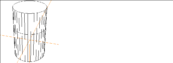
1. (CLICK-L) on GeoMenus>File>New Object>Cylinder.
Figure 10.9 A cylinder2. (CLICK-L) on faces on the element sensitivity menu.
3. (SHIFT-L) on the face on top of the cylinder, then (CLICK-L) on Extrude.
4. (CLICK-L) on segments on the element sensitivity menu.
5. (SHIFT-L) on one of the segments around the middle of the cylinder.
6. (CLICK-L) on Select Edge Loop.
7. (SHIFT-L) on the collection.
8. (CLICK-R) on Scale and (CLICK-L) on Object Midpoint for the scaling center.
Figure 10.12 Working with a collection
When Select Edge Loop Stops
The Select Edge Loop command stops when the loop meets a "Y" in the path:

Why else would you want to gather elements? In some cases, it makes sense to group elements into "parts." Once elements are grouped into parts, you can choose that part and perform various operations on it.
Defining Parts
Face Parts
Face parts group faces into logical units.
Vertex Parts
Vertex parts group points into logical units.
Creating a Part
1. Create a cube.
2. Collect the faces around the edge of the cube.
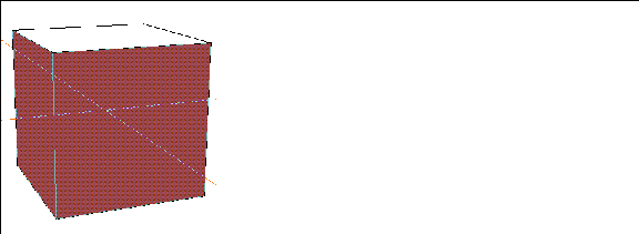
3. (SHIFT-L) on the collection, then (CLICK-L) on Add to Part.
4. (CLICK-L) on Make New Part.
5. Give the part a name in the dialog box that appears or simply use the default:

6. (CLICK-L) on the Make Part button.
Selecting the Part
To select the part you just made:
7. (CLICK-L) on bodies on the element sensitivity menu.
8. (SHIFT-L) on the cube, then (CLICK-L) on Parts.
Figure 10.16 Seeing parts associated with an object9. (CLICK-L) on the part you defined in step 5.
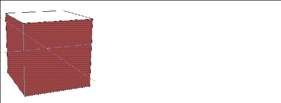
Adding Elements to a Part
You can add elements to a previously defined part; however, the elements you add must be of the same type (e.g., faces to face parts and vertices to vertex parts).
Let's add a face to the part you defined in step 5:
10. (SHIFT-L) on the face on top of the cube, then (CLICK-L) on Add to Part.
Figure 10.18 Adding an element to a part11. (CLICK-L) on the part you defined in step 5.
12. Select the part as you did in steps 7 through 9.
Figure 10.19 Selecting the modified part
Renaming a Part
If you used the default name (e.g., "4 faces" or "4 points"), you'll find that you may want to rename the part.
Parts can be renamed as follows:
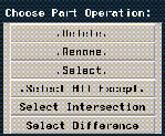
15. (CLICK-L) on the part you defined in step 5.
Figure 10.22 Give the part a name16. (CLICK-L) on the Rename Part button.
Removing Elements from a Part
Suppose you change your mind now, deciding that you don't want the top face to be in the face part you defined. How do you remove an element (or elements) from a part?
17. Collect the elements you want to remove from a part.
Figure 10.23 Removing an element from a part19. (CLICK-L) on the part you want to remove the element from.
20. Select the part as you did in steps 7 through 9 to verify that the element has been removed.
Deleting a Part
Deleting a part does not destroy the elements in the part; rather it deletes the logical connection between the elements.
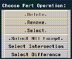
23. (CLICK-L) on the part you want to delete.
More about Parts
The previous discussion gives you a good working knowledge of how to create, modify, and remove parts from an object. As you may have noticed, there were additional options on some of the menus that were not explained in this section. For a detailed description of those options, refer to the N-Geometry Reference Guide.
 Another fine product from Nichimen documentation!
Copyright © 1996, Nichimen Graphics Corporation. All rights reserved.