As described earlier, an object is made up of two elements:
1. (CLICK-L) on objects in the element sensitivity menu.
2. Move the mouse over the object you want to transform in N-Geometry.
3. When the object you want to transform is highlighted, (SHIFT-L).
Each of the object-transformation operations is described in more detail in this section. Additional "utility" operations that can be performed on an object are described in the section "Object Utilities," on page 3-28.
Apply Transform
Applies the matrix transformations to each vertex on the object's body, then reinitializes the matrix, making its previously transformed position its home position. This has the effect of shifting the object to coincide with the object's home position without changing the apparent location of the object.
1. Create a tetrahedron and transform it away from the global center.
Figure 3.3 Transformed tetrahedron2. (SHIFT-L) on the object, then (CLICK-L) on Apply Transform.

Axis Move
Moves the object along a specified axis. (SHIFT-L) on the object, then choose the axis along which you want to translate it.
In Figure 3.6, we used Axis Move>X to move the sphere along the X axis.
Axis Scale
Scales the selected object(s) along a selected axis. Axis Scale has different capabilities, depending on which mouse button you use:
Copy From
This option lets you copy the transformation matrix from one object to the current object.
To copy a transformation matrix from one object to the currently selected object:
1. (SHIFT-L) on the object whose matrix you want to change.
3. (CLICK-L) on the object whose transformation matrix you want to copy.
Free Scale
Scales an object independently along each axis in the object's local coordinate system.
Home
Resets the object's transformation matrix back to its home position. The home position is by default the global center; if you have used the Set Home command to save a new home position, the transformation matrix is set to that position.
To see how the Home command works:
1. Create a tetrahedron and use Axis Move to transform it along the X axis:

2. (SHIFT-L) on the tetrahedron object and (CLICK-L) on Axis Scale>Y.
Figure 3.12 Tetrahedron object Axis Scaled along Y axis3. (SHIFT-L) on the tetrahedron object and (CLICK-L) on Home.
Local Skew
This option distorts an object along a selected local axis (x, y, or z).
Figure 3.14 Local skew along X axis
Figure 3.15 Local skew along Y axis
Figure 3.16 Local skew along Z axis
Move
Move the object freely in the x, y, or z direction. Move the mouse left and right to move in the X, up and down to move in the Y, and (HOLD-M) to move in the Z; which XYZ coordinate system is used depends on which mouse click you use:
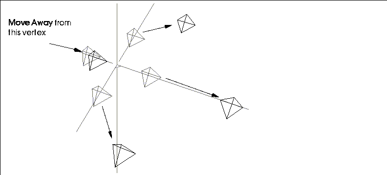
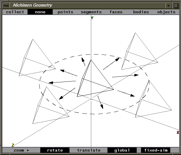
Move Away
Move Away scales the distance between two or more selected objects.
To scale the distance between several objects:
1. (CLICK-R) on objects in the elements sensitivity menu.
Figure 3.18 Original set of objects3. From the menu that appears, choose an anchor point from which all the selected objects are moved.
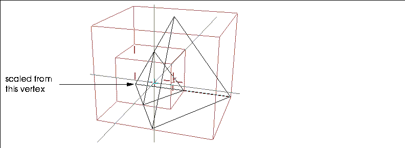
Choosing a point other than the global center will create different effects; for example, if you choose Select Element from the menu described above, then choose a point on one of the tetrahedra, the distance between the objects is scaled from that point, as shown in Figure 3.20:
Move Origin
The Move Origin command lets you move an object's origin without moving the object's body.
To move the origin of an object:
1. (CLICK-L) on the object whose origin you want to move.
Figure 3.21 Left, cube with unaltered origin; right, (CLICK-L) on Move Origin to move the origin interactively
If you want to select the position for the origin from a menu:
3. (CLICK-L) on the object whose origin you want to move.
Figure 3.22 Left, cube before Move Origin; right, (CLICK-L) on Move Origin and (CLICK-M) on Origin (to select global origin)
Move To
Move To moves an object's center (or a selected point on the object's body) to another point.
Consider an example like the one in Figure 3.24; you could use this feature to make the tetrahedron's center co-local with one of the corners of the cube:
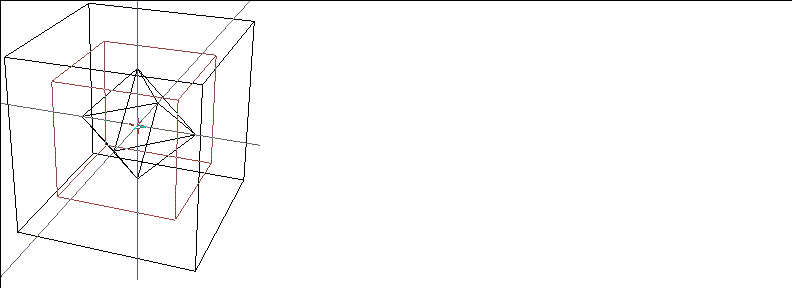
1. (SHIFT-L) on the tetrahedron.
3. (CLICK-L) on Select Element.
4. (CLICK-L) on the cube's upper right corner.
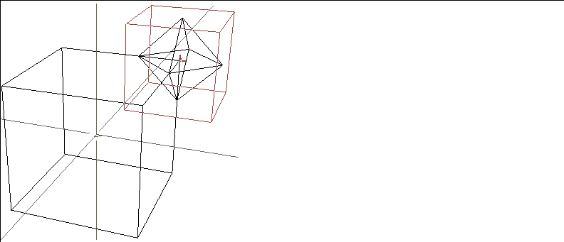
If you (CLICK-M) on Move To, you are given even more flexibility in moving an object.
1. (SHIFT-L) on the tetrahedron.
3. (CLICK-L) on Select Element.
4. (CLICK-L) on the tetrahedron's upper right corner.
6. (CLICK-L) on the cube's upper right corner.
Figure 3.25 You can align objects based on some element of the object as well (like a point)
Plane Move
Moves an object around on a selected plane, with local rotations perpendicular to the chosen plane.
Remember
Lets you temporarily save the transformation matrix of the currently selected object. To remember a transformation matrix:
1. (SHIFT-L) on the object whose transformation matrix you want to remember.
Figure 3.27 Remember
Rotate
Rotates the object around a selected axis.
Scale
This option scales the object along three axes uniformly in the object's local coordinate system.
Figure 3.29 Object scaled around object center with (CLICK-L)
Scale to Fit
This operation scales one object to match the size of another object.
Scales the scale portion of an object's transformation matrix to match that of another object. In Figure 3.31, assume that you want the sphere to be the same scale as the tetrahedron:

1. (SHIFT-L) on the sphere object.
3. Choose the target object from the list that appears.
Note that the object is translated as well.
Select
The Select command lets you replace the current object's transformation matrix with a previously remembered matrix.
Figure 3.33 Using a "remembered" transformation matrix
See the section "Remember," on page 3-20 for instructions on how to save a transformation matrix.
Figure 3.34 Transformation matrix operations
Skew
Skew resembles Local Skew, but the axes are defined according to the axes of the superior object.
To see how Skew works, try this:
1. Create a new tetrahedron object.
2. (SHIFT-L) on the object and (CLICK-L) on Axis Move>X.
The object utilities are some generalized features that you commonly perform on an object:
Object Utilities
Each of these operations is described (in alphabetical order) in the sections below.
Backfacing
Toggles the backfacing on/off for the selected object's body. If turned on, N-Geometry displays only those faces whose normals point toward the camera.
To toggle the backfacing of an object's body:
Copy
Makes a discrete copy of the selected object(s). For more information, see the section "Copy," on page 2-59.
Delete
Deletes the selected object(s) from the scene. For more information, refer to the section "Delete," on page 2-68.
Describe
Prints out the object's transformation matrix in the UNIX shell window from which N·World was started. You may find it helpful at times to be able to read the transformation matrix of an object (for example, to see if an operation you performed actually did what you think it did).
A transformation matrix looks something like this:
32 (move)
1.0000 .0000 .0000 .0000
.0000 1.0000 .0000 .0000
.0000 .0000 1.0000 .0000
12.26 2.00 5.50 1.0000
Export
Exports the selected object in one of the formats described in the section "Export," on page 2-53.
Hard Edging
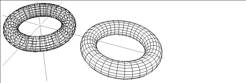
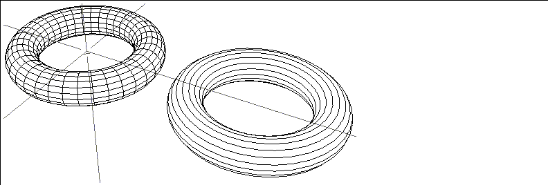
Hard Edging toggles the display of edges whose adjacent faces meet at an angle greater than a specified value. This option is useful when animating (with N-Dynamics) if you want to turn off the display of some edges. This operation does not affect the geometry of the object, only its display!

Figure 3.39 shows an object in its original state, and with hard edging turned on to reduce the number of displayed edges:
List
The List command displays a list of elements in the selected object(s). This list is printed in the UNIX shell window from which N·World was started.
A list for a complex object might look like this:
----------------- SELECTED OBJECTS --------------------
"2-Subobjects"
"Copy of Torus" #<POLYHEDRON 94>: 648pts 1296edges 648faces.
"Torus" #<POLYHEDRON 91>: 648pts 1296edges 648faces.
Element totals: 1296 pts, 2592 segments, 1296 faces.
Local Axes
Toggle the display labeled local axes of terminal objects. Displaying local axes makes it easy to see where an object's origin is (see Figure 3.40.) This feature makes it easier to visualize transformations, many of which are relative to the local axes.

This is identical to the Local Axes command described in the section "Local Axes," on page 6-5.
Multiply
Creates multiple versions of the selected object(s), allowing you to create complex lattices of various shapes. For more information, see the section "Multiply," on page 2-61.
Normals
Toggles the display of normals for the selected object; you can display normals for points, edges, or faces, depending on which button you click:
Figure 3.41 Left, cube with point normals displayed; middle, edge normals; right, face normals
Points
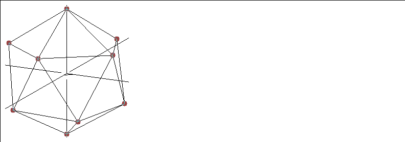
The Points operation toggles highlighting of the object's vertices (see Figure 3.42.) This type of presentation is especially useful with wires or with objects that have many vertices with only two adjacent edges, which might appear to blend together if the angle between them is fairly small.
The highighted point radius can be set using Utilities>Preferences>Objects>Point Display Radius.
Reinstance
Creates a new instance of the selected object; the reinstance and the original object share the same body, so that changes made to the body in one place are reflected in every reinstance. For more information, see the section "Reinstance," on page 2-59.
Rename
Renames the selected object. When you select the object to be renamed, a dialog box appears with the object's current name in it.

Restructure
Restructures the selected object into a different level in the object hierarchy. Restructuring, and object hierarchy in general, are described in more detail in the section "Restructure," on page 7-2.
Save
Save the selected object. This is identical to the Save command described in the section "Save," on page 2-50.
Sensitivity
Toggles the sensitivity on/off for the selected object's body. If turned on, the object's body is made temporarily "insensitive;" it cannot be modified (with any of the body modification operations). The insensitive body is displayed in a lighter gray in the N-Geometry window.
To toggle the sensitivity of an object's body:

Shading
Toggles the shading on/off for the selected object. If turned on, the object is hardware-rendered in the N-Geometry window using GL Shade.
To toggle an object's shading:

Stand-ins
The Stand-ins command displays a "substitute" box instead of the object itself whenever you move the camera or transform the object.
This is identical to the Stand-ins command as described in the section "Stand-ins," on page 6-8.
Visibility
Makes the selected object invisible.
To toggle an object's visibility:
For more information, see the section "Visibility," on page 6-8.
 Another fine product from Nichimen documentation!
Copyright © 1996, Nichimen Graphics Corporation. All rights reserved.