[N-World Contents] [Book Contents] [Prev] [Next] [Index]
Dynamic Operations
In an N-Dynamics script, you layer different operations, one on top of another, to move objects, animate skeletons, perform paint operations-in short, to animate almost any function available in the N·World suite of products.
Editing Channel Parameters
Each operation occupies its own channel, which is a visual representation of the operation's position in the script:
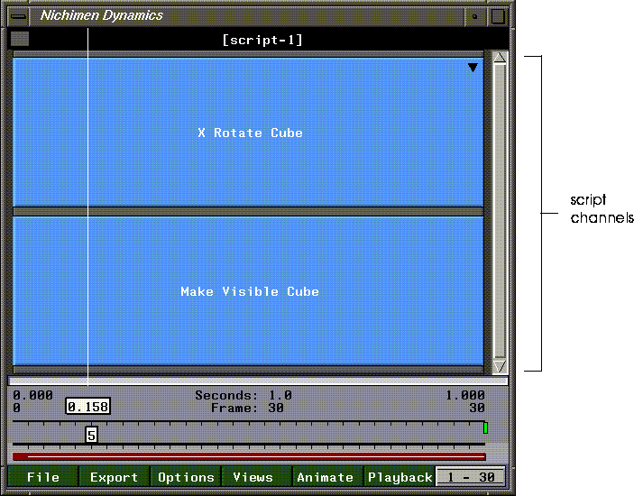
Figure 5.1 Script channels
A script lasts a set number of frames. When you animate a script, channels are executed from top to bottom. When all channels have been executed, the frame counter is incremented and all channels that exist at the next frame are executed.
Channel Properties
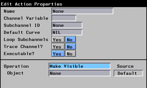
All channels share a number of parameters. These channel properties appear at the top of the Edit Action Properties dialog box. To view an action's properties, (CLICK-M) on an action in the script.
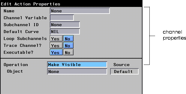
Figure 5.2 Channel properties
- Name specifies the label name for the channel-this is the name that
appears on the channel in the script editor. By default, the channel name is equal to the "operation + object" (e.g., Make Visible Cube). This field lets you assign a more descriptive name to the channel like "bounce ball" or "spin".
- Channel Variable specifies a name for the value returned by the action. Some actions can perform operations which return a value (which can be referenced by this name from other operations).
- Subchannel ID indicates the dynamic value contained in the channel.
- For example, if you set up a subchannel to do an X-Rotate on a cube, the Channel ID is set to ANGLE, since the dynamic value is used to set the angle of rotation.
- In another example, consider an operation like Subtract. It automatically creates two sub-curves called NUMBER1 and NUMBER2. When you animate, this operation subracts NUMBER2 from NUMBER1. If you later realize that you wanted to subtract NUMBER1 from NUMBER2, you could simply change the Channel IDs to subract the second channel from the first.
- Default Curve defines the default curve type for any subchannels added to this parent channel.
- Loop Subchannels? causes any subchannels that are shorter than the length of this channel to repeat over the length of this channel.
- This can be very useful, for example, if you animate a walk cycle that takes only one-tenth the length of the script, but want the cycle to repeat over the length of the script. If you turn Loop Subchannels on for the parent action of the action that animated that walk cycle, it would be repeated 10 times over the course of that script.
- Trace Channel? lets you display the value returned by the channel in the LISP listener window. This is used primarily with the Basic Functions in the Dynamics module, as their purpose is often to produce a value used by another action. This feature is typically used for debugging a script that is not doing what you expect.
- You can display the value returned by the channel over time (as the script animates), or for a single frame (by using (CLICK-L) on the frame range area).
- Executable? toggles the "executability" of the current channel. This can be used if you add subchannels to a parent channel, but want the parent channel to function only as a placeholder; set Executable to No for the parent channel, but leave all the children channels executable. (Any time you add subchannels to a channel, those "children" channels inherit all the parameters set in the parent channel. This feature lets you create a parent channel with the desired defaults, from which you can create multiple children with their defaults set to match the parent.)
Action Properties
While there are a number of parameters that are common to all channels, each action may require a different set of parameters. While the channel properties are specified above the black line, in the Edit Action Properties dialog box, the operation properties are specified below the black line.
Depending on the type of operation you select, a number of additional parameters appear in the Edit Action Properties dialog box; the parameters required for each operation are discussed in the appropriate sections below.
Local, Inherited, and Dynamic Values
Many N-Dynamics operations let you specify whether the supplied parameter values are local, inherited, or dynamic.
To change the source of the value for the parameter, (CLICK-L) in the text box next to the parameter.
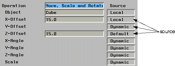
Figure 5.3 Changing the source for operation values
The following dialog box appears:
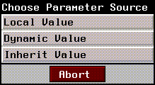
Figure 5.4 Selecting a source
N-Dynamics Operation Classes
N-Dynamics' operations are grouped into different modules. Each module corresponds to an individual product in the N·World suite of products. In N--Dynamics, each module contains a number of operation classes, and each class contains a number of operations.
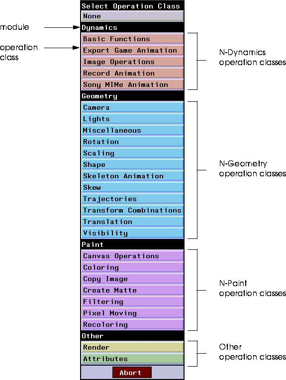
Figure 5.5 The Dynamic Operation Class menu
Operations are grouped into classes according to the type of function they perform. In the Scaling operation class (in the N-Geometry module), for example, there are a number of operations that let you scale objects in many different ways:
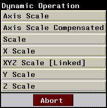
Figure 5.6 Scaling operations
When you select an operation, the appropriate parameters are displayed in the Edit Action Properties dialog box:
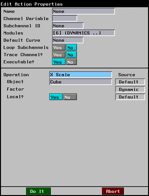
Figure 5.7 Parameters for X Scale
You enter appropriate values for each parameter, then (CLICK-L) on Do it when you're done.
The name of the channel in the script editor changes to reflect the operation you have selected. If the operation affects an object (as it typically does) that object's name appears in the channel as well.
The following pages describe each of the dynamics operations.
Dynamics Operations
Dynamics operations are those that do not directly perform operations in other modules like N-Geometry or N-Paint; rather they provide additional control over aspects of N-Dynamics itself.
There are operations that perform mathematical operations on other values, that control flow of the script itself, or which can limit certain operations to be performed only when certain conditions exist.
Basic Functions
This operation class contains the more "programmatic" operations in N-Dynamics.
Add
The Add operation has two dynamic values. An Add operation could be inserted in place of a dynamic value for another action; for example, if you wanted an object to rotate a number of degrees equal to two dynamic values, you could set up an action that looked like this:
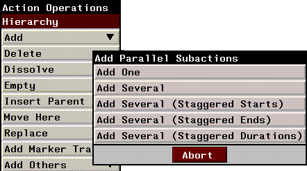
Figure 5.8 Using an Add action as a dynamic value
The value in the first curve would be added to the value of the second curve (at each frame), and the object would be rotated that number of degrees.
The value returned by the Add operation can also be referenced using the Channel Variable assigned to the Add channel.
The following parameters can be specified:
Call Script
Calls the specified dynamics script from within the current script. If you are coordinating a large number of complex motions in your script, you may find it useful to animate the motions in individual scripts, then create a "main" script which calls those other scripts as appropriate.
For example, if you created a main script to do the bulk of your animation, then created a second script to animate the walk cycle for a character, you could simply call the walk cycle script whenever you wanted to use it.
Also, because the script can be more modularized, debugging problem areas of the script is easier.
In the same example, if you found an error in the walk cycle script, you could simply make a change to it, then reanimate the main script, and the motion would be corrected every place the walk cycle script was called.
Divide
This operation is identical to the Add operation described in the section "Add," on page 5-9, except that the two dynamic values are divided rather than added. Divide divides the value in Number 1 by the value in Number 2.
Do if then else
This operation performs one action if the result of a test is true, or another if the test is false. To use the operation, you need to insert a Do if then else parent channel, with three subchannels:
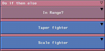
Figure 5.9 A typical Do if then else operation
Do when
This is similar to the Do if then else operation above, except that actions are only performed only if the result of the test channel is true.
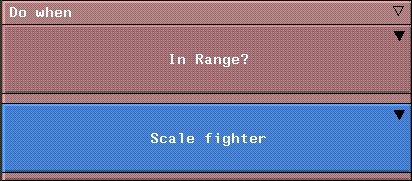
Figure 5.10 A typical Do when operation
You can add multiple actions to be performed either by grouping them in the first subaction immediately after the test channel, or adding them at the same level.
Evaluate Lisp Form
Evaluates the specified LISP form.
Get Variable Value
This action retrieves the Channel Variable from another channel. It is typically used to replace a curve.
For more on replacing a curve with a Get Variable Value operation, see the section "Replace with Variable," on page 4-39. Also, refer to the N-Dynamics Tutorial.
In Range?
This is a condition operation, typically used as a test case in the operations Do if then else and Do when.
In Range? checks to see if a variable or result is within a certain range. If Value is between Min and Max, the operation returns a true result, if not, it returns a false result.
Less than?
This is a condition operation, typically used as a test case in the operations Do if then else and Do when.
It tests the value in Number 1 against the value in Number 2; if Number 1 is less, the operation returns a true result, if not, it returns a false result.
Mix
Mixes the two values specified in Number 1 and Number 2, using the mix factor specified in Mix Amount:
To see a sample of the effect, add a derived curve to the channel, then create a Mix Amount that ramps from 0 to 1 over the length of the channel. Create a sketched sine wave curve in the first channel, and a sketched sawtooth curve in the second channel. Finally, insert a derived curve and recompute it to show how the two are mixed:
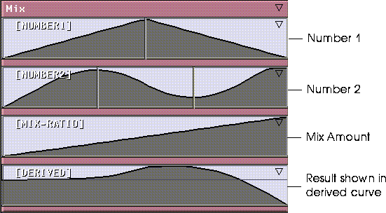
Figure 5.11 Mixing two curves and showing the result in a derived curve
Note that in the derived curve channel, the mix used mostly data from the sawtooth curve at first, but gradually mixes in more of the sine wave curve.
Multiply
This operation is identical to the Add operation described in the section "Add," on page 5-9, except that the two dynamic values are multiplied rather than added. Multiplies the value in Number 1 by the value in Number 2.
Pause
Temporarily pauses the execution of a script. When a Pause operation is encountered the following dialog box is displayed:

Figure 5.12 Pausing a script
Pause is useful if you want to perform some manual operation at each frame of a script (e.g., some rotoscoping type of task), then resume execution of the script. All other N·World products are still active when the script is paused.
Print Value
Prints the dynamic value in its subchannel to the Nichimen Message Window (automatically displayed on screen if required). You may use the replace with variable command on the dynamic value for the operation to print the value of a selected variable:

Figure 5.13 A typical Print Value operation
Renormalize
Renormalizes the values in the Input channel using the Min and Max values supplied. You could use this operation, for example, to convert values between 0 and 1 to values between 0 and 360 if you used the parameters below:
Return Value
This operation does nothing more than return a value based on the content of its subchannels. This channel is normally inserted as a parent channel around a series of sequential curves (since they must be contained in a channel, and by default they do nothing more than return a value).
For example, you could also use this operation if you wanted all your operations to use the same curve data. You'd add a Return Value channel (or several), assign them variable names, then in operations requiring a curve, you could replace the curve with a Get Variable Value operation and specify the variable name assigned to the curve in the Return Value operation.
Subtract
This operation is identical to the Add operation described in the section "Add," on page 5-9, except that the two dynamic values are subtracted rather than added. Subtracts the value in Number 1 from the value in Number 2.
Timewarp
Timewarp sets a curve that affects the apparent flow of time in a script. For example, if you have a script that manipulates a number of objects, and wanted to slow down the entire animation at the beginning, you could apply a Slow-In curve on the whole script by using Timewarp.
In order to do this, add a channel to hold the Timewarp operation at the top of the script. The script affects all channels below it in the same parent channel:
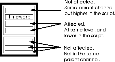
Figure 5.14 Placing a Time Warp operation
Consider the two "extremes:"
As each frame executes, N-Dynamics passes a value to each channel from top to bottom, telling it the current frame. When it encounters a Time Warp channel, that value is temporarily replaced by the value in the curve. The value of the curve at that frame tells N-Dynamics what frame to execute for any affected channels (as described above).
So in the second example below, at frame 1, the value in the curve is 1. This means that N-Dynamics now thinks it should execute the frame at 100% of the length of the channel. The next frame is a slightly lower value (say 95%), so the frame corresponding to that percentage of the length of the time warp channel would be executed.
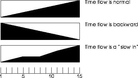
Figure 5.15 Sample Time Warp
Export Game Animation
This operation is intended for use with the Nichimen Game Exchange. This operation records the information required to send Game Exchange animation data for the selected object. Animation data can be output to a specified directory and filename.
Refer to the Game Exchange User's Guide for more information on the actual animation data format.
Image Operations
This operation class contains "image management" operations; operations that don't affect the image directly (such as recoloring it), but rather let you do things like copy from one directory to another, load images into windows, save images in windows to file, and write movie files.
Copy Indexed Images
Copies a series of indexed images from one directory to another:
Load Image into Window
Loads an image into the background of the specified window.
Table 5.16 Load Image into Window parameters
|
Parameter
|
Dynamic?
|
Description
|
|---|
|
Directory1
|
No
|
The directory that contains the image to be loaded.
|
|
Name
|
No
|
The name and format of the images being loaded into the window; you can load TIF, RGB, or TPX files. The filename is used to determine which files are to be loaded if you load a sequence of images. The default filename, "from-0001.tif" has four parts to it:
from is the base file name
"-" is the character that separates the base file name from the index number. This may be either a dash or a period.
0001 indicates the amount of padding used in the index (images are named 0001, 0002, etc.)
.tif is the extension part of the filename.
(CLICK-R) to choose the input image from a list of images in the specified directory.
|
|
Increment
|
No
|
An increment used when loading files. If the files are indexed, a new image is loaded each frame.
An increment of 1 loads images in sequence, an increment of 2 loads every other image, and an increment of 5 would load every 5th image. An increment of 0 loads only the specified image.
|
|
Window
|
No
|
The window the image should be loaded into. Images can be loaded into the 3D Camera window (N-Geometry), the Render Window (N-Render), or the Paint Canvas (N-Paint).
|
Record Movie Audio
Inserts an .aiff audio file into a movie.
- Note. You must have a Record Movie Image operation higher in the script than this operation. Record Movie Image creates the movie file, and this operation expects such a file to exist when it is executed.
Record Movie Image
Writes out an SGI movie (.clip) file that can be played back with the SGI movie player utility.
To play back a .clip file, use the following command:
movieplayer movie.clip
where "movie.clip" is the name of your file.
Save Window to File
Saves the contents of the specified window to a file.
Record Animation
Generates data required to export animation to the Nintendo 64 and Sega Saturn game platforms using N64 Express and Saturn Express tools.
Table 5.20 Record Animation parameters
|
Parameter
|
Value
|
Dynamic?
|
Description
|
|---|
|
Hierarchy Type
|
|
No
|
Determines the level in an object hierarchy for which transformation matrices are generated.
Consider the following object level hierarchy, which shows the levels at which transformation matrices are generated:
Upper Arm Group G S
Upper Arm F G
Lower Arm Group G S
Lower Arm F G
Hand Group G S
Hand F G
Where F=flat, G=geometry, S=skeleton. Each of thehierarchy types is described in the sections below.
|
|
|
flat
|
|
Pre-multiplied transformation matrices are generated for each terminal object in the hierarchy.
|
|
|
geo
|
|
Transformation matrices are generated for each object (or objects), just as in N-Geometry. If there is an object hierarchy, transformation matrices are generated for each subobject in the hierarchy; to determine the position of a terminal object, matrices in the hierarchy must be multiplied.
|
|
|
skeleton
|
|
Pre-multiplied transformation matrices are generated for each non-terminal object in the hierarchy. (This is basically the opposite of flat, above.)
If you specify skeleton as the hierarchy type, you are also prompted to specify which skeleton's animation you want to export.
|
|
Which Objects?
|
|
|
|
|
|
Visible
|
|
Generated data for all visible objects in N-Geometry.
|
|
|
Choose
|
|
Generate data for objects selected from an object list.
If you specify object as the hierarchy type, you are also prompted to specify which skeleton's animation you want to export.
|
|
Record Camera?
|
|
No
|
Record camera information as well.
|
|
Record Light?
|
|
No
|
Record light animation information as well (e.g., position, angle, etc.)
|
Sony MIMe Animation
Generates data required to export animation to the Sony PlayStation. For more information, see the PlayStation Express User's Guide.
Geometry Operations
Camera
Camera operations apply only to cameras, and their arguments default to those of the current camera.
Set Aimpoint
Sets the aimpoint for the camera using Cartesian coordinates.
Set Aimpoint to Object Center
Aims the camera at an object. This defaults to 1 (so that the camera starts out and ends up pointing at the specified object).
Set Aimpoint X
Sets the aimpoint of the camera. Similar to Set Aimpoint except that you modify only the X value of the aimpoint. Based on the curve data supplied, the camera's aimpoint moves along the global X axis.
Set Aimpoint Y
Similar to Set Aimpoint X, except that the value defined is for the aimpoint along the global Y axis.
Set Aimpoint Z
Similar to Set Aimpoint X, except that the value defined is for the aimpoint along the global Y axis.
Set Camera Format
This operation is useful for defining the characteristics of your viewport (i.e., aspect ratio) and is particularly useful when creating rendered scenes you wish to composite, for example, with live footage. If you know the camera settings used to generate the live footage, you can select that format and be sure that the two will match.
- Note. Positioning the mouse over any of the format names listed in the pop-up menu displays the aspect ratio of that format in the mouse documentation line.
Set Hither Distance
The hither distance is the closest distance from the camera at which objects are still displayed. If they move closer, they "drop out" or are no longer displayed.
Set View
Sets the camera's position. You can use the operation to make the camera's position constant throughout the length of the script, or to move it from one view to another.
By opening the VIEWER subchannel, you can specify a beginning and ending camera view in the Start Value and End Value fields. You could also specify a single camera view for the length of the script using a hold type of curve and specifying a single start value.
Views may be selected from a menu of saved views or copied from the current camera view.
- Note. You can add cues to the curve, then tie a camera view to each cue. The curve data in this channel, however, does not reflect the x, y, and z changes in the camera's position; it is only an aid in seeing that cues have been defined at certain points in the channel.
Set View Angle
Adjusts the view angle of the camera.
Set View from Object
Enables you to "attach" the camera to an object. This operation positions and orients the camera onto another object's local origin, and points it along the specified axis.
Set Yon Distance
The yon distance is the distance from the camera at which objects "drop out" or are no longer displayed.
Lights
The Lights operation class lets you work specifically with lights;
You can animate a light's geometric properties by using geometric operations such as Rotate And Move, or you can the operations under the Lights operation class.
Set Light Aimpoint
Lets you aim a spotlight at a point in space, specified using Cartesian coordinates.
Set Light Aimpoint to Object Center
Lets you aim a spotlight at the center of an object, or using the curve channel, move a spotlight toward an object. This operation is useful for setting up a spotlight so that it follows (or catches up to) an object that is moved by some other operation.
Set Light Brightness
Sets the brightness component for the selected light.
Note that the brightness for a light can be scaled to values beyond 1 (particularly useful for animating dark scenes or forcing a light to wash out a scene).
Set Light Color
Sets the color component for the selected light.
Note that by using the curve data in association with the change in beginning and ending colors for the light, you can create dramatic lighting changes. A light could start out red, maintain its color through most of the script, then change quickly to green at the end.
Set Light Falloff Angle
Changes the falloff angle for the selected spotlight over time. If you specify a dynamic value, you can use this operation to gradually soften a light (or make it harder, depending on the curve data in the Falloff Angle subchannel).
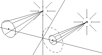
Figure 5.16 Left, original light; right, light with modified light falloff angle
Set Light View Angle
Changes the spot angle for the selected spotlight over time. If you specify a dynamic value, you can change the diameter of a spotlight over time (using the curve data in the View Angle subchannel).
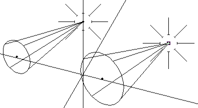
Figure 5.17 Left, original light; right, light with modified view angle
Miscellaneous
Distance from Location
Returns an object's distance from a specified location.
Distance from Object
Returns the distance between two objects.
This can be used to determine when one object is approaching another; you could, for example, displace a character (e.g., make him "duck") whenever another object came within a certain distance of the character's midpoint.
Distance from Plane
Returns an object's distance from a specified plane.
This can be used to determine when one object is approaching the selected plane.
Export Object
Enables you to set up a channel that exports an object at each frame over the course of the script. This is useful, for example, if you want to displace multiple versions of an object that is somehow being deformed over the course of the script.
Objects are written out with the following syntax:
object-name.0001.obj
where 0001 is the frame number and obj is the automatically appended extension. (Note that you can (CLICK-L) on a single frame to export the object for only one frame.)
Multiple Operations
Displays a menu containing all N-Dynamics operations. To select operations, (CLICK-L) on each operation to highlight it. After selecting the desired operations from the menu, (CLICK-L) on Do It.
If more than one operation is selected from the menu, a separate channel is created for each operation; each channel is a subchannel to the multiple channel operation itself.
Object Size
Returns the size of an object, expressed in global units.
It is mainly used for some of the Basic Operations. For example, you could use a Do if then else operation to force an object to disappear from the scene if it became so small that it was inconsequential.
Perform Frame Action
Lets users conversant in LISP apply a form directly to an object in the script.
The referenced variable for the object in the LISP form must be "$object".
Rotation
The rotation operations rotate an object so that it is aligned with another selected object, or around some arbitrary axis specified by the user.
Align To
Aligns the object's local +Z axis with the specified values. (You must (CLICK-M) on the curve channel to set the beginning and ending values, or to specify any cues.)
This could be used to make a character's "face" turn from one point in space toward another.
Align to Object Midpoint
Aligns the object's "front" (+Z) with another object.
This could be used to make a character's "face" turn to follow an object, such as a flittering butterfly.
Align to Object Origin
Same as above, but points the camera to the object's local origin rather than its midpoint.
- Note. An object's origin is not necessarily its midpoint; for example, if you bake an object once you have applied some transformation, its origin is realigned with the global origin.
Quaternion Rotate
Rotates the selected object using a quaternion algorithm, which is particularly useful for avoiding "gimbal lock" (which can cause the camera to "flip" when it is closely aligned with one of the global axes.
To use the Quaternion Rotate function with an object, insert several cues into the curve channel for the operation. Transform the object into a different position, then (CLICK-M) on a cue and (CLICK-L) on Copy Orientation. This copies the object's orientation into the cue.
When you animate the script, the position of the object interpolates between cues.
Rotate
Rotates the object a specified number of degrees around a specified axis.
Normally, this operation is used with an object to which you have attached a rotation axis (using the Add Attachment command in N-Geometry).
X Rotate
Rotates a cube around either its local X axis or the global X axis.
XYZ Rotate [Linked]
Rotate an object around the x, y, or z axes (either local or global). A subchannel is created for each rotation axis; in addition, a marker track is inserted in the channel so that cues in the different curve channels can be easily tied to one another:
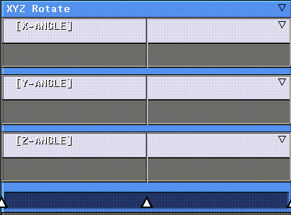
Figure 5.18 A subchannel is created for each rotation; a marker track is automatically inserted so that cues can be tied together
For information on how to link cues together using the marker track, see the section "Move, Scale and Rotate [Linked]," on page 5-56.
Y Rotate
Rotates an object by a given angle about the specified Y axis. See "X Rotate," on page 5-39.
Z Rotate
Rotates an object by a given angle about the specified Z axis. See "X Rotate," on page 5-39.
Scaling
The Scaling operation class scales objects along a given axis (either local or global) or around a selected point.
Axis Scale
Scales an object along a specified axis (the default is the object's local Y axis).
The object is stretched along the specified axis; its dimensions in the other two axes is not affected.
Axis Scale Compensated
Squashes-and-stretches an object along a specified axis. This operation differs from Axis Scale in that the object scaled retains its volume as it is squashed or stretched along the specified axis.

Figure 5.19 As object is stretched or squashed, it retains its volume
You could use this, for example, to animate an object colliding with a surface; you would want it to "squash" along the axis of its movement toward the object it collided with, but retain its volume.
Scale
Scales the selected object by the specified factor.
X Scale
Axis scales the selected object along the specified X axis (either local or global)
XYZ Scale [Linked]
Scales the object independently along the x, y, and z axes (either local or global). A subchannel is created for each axis; in addition, a marker track is inserted in the channel so that cues in the different curve channels can be easily tied to one another, as shown in the section "Move, Scale and Rotate [Linked]," on page 5-56.
Y Scale
Scales the object along the Y axis. See the section "X Scale," on page 5-43.
Z Scale
Scales the object along the Z axis. See the section "X Scale," on page 5-43.
Shape
The Shape operation class is used to animate displacements created in N-Geometry, and to swirl, taper, or twist objects.
Apply Transform
Applies the transformation to all vertices on the object, aligning the object's local origin with its superior's origin (typically the global origin).
- Note. This has serious consequences to your animation! Because operations are based on an object's transformation matrix, using Apply Transform on the object creates a whole new "offset" from which subsequent actions are performed.
Displace Shape
Displaces an object to a known state. You should have saved at least one relative or rotational displacement on the object to use this operation, and should have included a Set Shape operation on a channel higher in the script. (You may also want to use the Displace Shape [Template] operation, described below.)
Displace Shape [Template]
Creates the proper subchannels to set up an animation based on saved displacements for an object. (This is a combination of the Displace Shape and Multiple Displace Shape operations.
After choosing this operation type, you are prompted to enter the following information:
When you (CLICK-L) on Do It, the following subchannels are created:
Figure 5.20 A template with channels for two relative displacements
For information on how to link cues together using the marker track, see the section "Link to Marker," on page 3-27.
Multiple Displace Shape
Lets you animate using multiple displacements in the same channel (similar to a gesture, as described in the N-Geometry Reference Guide). You should have defined multiple displacement states for this object in N-Geometry before using this operation, and should have included a Set Shape operation in a channel higher in the script before using it. See the Displace Shape [Template] described above.
For each displacement specified, a separate curve channel is generated, which controls how much of the displacement is applied to the shape.
If you had defined two displacements for a character, one of a frowning face called "frown" and one of a smiling face called "smile," you could animate the face from one state to another with a single action.
In the frown channel, you could specify a linear curve with a start value of 1 and an end value of 0. In the smile channel, you could use another linear curve with a start value of 0 and an end value of 1. When animated, the character would start out in its frown state, but gradually move toward the full smile displacement at the end of the script.
Resmooth
Resmoothes a patch body or an object that has been smoothed with history. For details on patch bodies or smoothing with history, see the N-Geometry Reference Guide. Typically, when you create a copy of an object that has been smoothed with history, you manipulate the lo-res version of the object, then animate the hi-res version.
Set Shape
If you are using any of the following operations, you need to use this operation to specify the base shape from which the displacements are measured:
The Set Shape operation should come before either the Displace Shape or
Multiple Displace Shape operations in the script. See also the section "Displace Shape [Template]," on page 5-45.
Swirl
Swirls the body of an object. For a more complete description of what Swirl does to an object, refer to the N-Geometry Reference Guide.
- Note. This operation should be immediately preceded by a Set Shape operation to set the base shape of the object being deformed.
Taper
Tapers the body of an object. For a more complete description of what Taper does to an object, refer to the N-Geometry Reference Guide.
- Note. This operation should be immediately preceded by a Set Shape operation to set the base shape of the object being deformed.
Table 5.61 Taper param1ters
|
Parameter
|
Dynamic?
|
Description
|
|---|
|
Object
|
No
|
The object to swirl.
|
|
Factor
|
Dynamic
|
The percent to scale the polyhedron along each of its axes. The default is a taper of (1, 1, 1) for the x, y, and z axes, respectively. This default does no scaling. To taper an object symmetrically by A along the y axis, the components factor should be (A, 1, A).
|
|
Axis
|
No
|
The global axis that the taper proceeds along. The default is y.
|
|
At Distance
|
Can be
|
|
|
Center
|
No
|
The reference point on the taper axis at which the polyhedron is or would be tapered the specified angle. The default is the highest point of the polyhedron in y.
|
|
Power
|
Can be
|
The exponential power of the rate at which the taper proceeds. The default power of 1.0 power creates a linear taper. A lower power, such as 0.5, tapers quickly near the center, then more slowly near the ends. A higher power, such as 2.0, tapers slowly at the beginning and then more quickly near the ends.
|
|
Symmetric?
|
No
|
Determines whether the tapering occurs symmetrically around the center of the object.
|
Twist
Twists the body of an object. For a more complete description of what Twist does to an object, refer to the N-Geometry Reference Guide.
- Note. This operation should be immediately preceded by a Set Shape operation to set the base shape of the object being deformed.
Skew
Skewing is the process that modifies an object along a local axis using the distance from the object to its origin in X, Y, and Z. For example, skewing can transform a typeface into italic form, or a rectangle into a parallelogram. A typical skewing specification might slide points in the Z direction according to their X-coordinate values. You could make such a specification to transform an airborne bird's wings from straight to swept-back as it dives toward the earth.
There are six ways to skew in XYZ space, and there is a dynamic operation for each:
Skew along X by Y
Skews the object along the X axis, around the Y:

Figure 5.21 Left, original cube; right, skewed along X by Y
Skew along X by Z
Skews an object along X by a factor of Z (local or global).

Figure 5.22 Left, original cube; right, skewed along X by Z
Skew along Y by X
Skews an object along Y by a factor of X (local or global).

Figure 5.23 Left, original cube; right, skewed along Y by X
Skew along Y by Z
Skews an object along Y by a factor of Z (local or global).

Figure 5.24 Left, original cube; right, skewed along Y by Z
Skew along Z by X
Skews an object along Z by a factor of X (local or global).

Figure 5.25 Left, original cube; right, skewed along Z by X
Skew along Z by Y
Skews an object along Z by a factor of Y (local or global).

Figure 5.26 Left, original cube; right, skewed along Z by X
Skeletal Animation
The Skeletal Animation operations are described in more detail in the Skeletal Animation System Reference Guide.
Trajectories
You can create paths called trajectories in N-Geometry, then use N-Dynamics to move objects along those paths. There are three N-Dynamics operations for moving any object (or the camera) along a trajectory.
Trajectories are encoded and edited like wires, however, the nodes on the wire are actually control points for a B-spline or interpolating spline "flight-path" in three dimensions. The nodes and segments of the control shape can be moved, deleted, cut, or edited in any other way, and the computed spline path is automatically updated to reflect these changes.
The position of an object along the trajectory is controlled by changing the value in the fraction subchannel for the sequence.
Note, however, that a linear interpolation from the start to the end of the curve will not produce motion along the trajectory at a constant speed. An object's speed along a trajectory is controlled by the relative spacing of the control points along the trajectory. Where the control points are closely spaced (perhaps to define a sharp bend in the trajectory) the motion slows down. Where the control points are widely spaced, the motion speeds up. This results in a natural-looking acceleration and deceleration effect, which actually depends on the sharpness of the trajectory. Of course, you can always override by using a curve-type other than linear for the sequence.
All three trajectory operations take a set of arguments in common:
Fly along Trajectory
Moves an object to a fractional position along a trajectory object. Orientation is computed so the heading and elevation of the object matches the tangent to the trajectory at that position.
With Fly Along Trajectory, banking (local Z-axis roll) is computed to match the tightness of curvature of a point slightly ahead of the current position on the trajectory (allowing for the effect of anticipation). This point is at the point
Fraction + Bank Parameter along the trajectory. The amount of banking computed can be scaled up or down by the bank-scaling factor. A negative factor here can be used to give the effect of a car or boat rolling around the outside of a turn, rather than an aircraft banking into a turn.
Move along Trajectory
Moves an object to a fractional position along a trajectory object. The object retains its current orientation and is simply translated to each new position on the path.
Orient along Trajectory
Moves an object to a fractional position along a trajectory object. Orientation is computed so the heading and elevation of the object matches the tangent to the trajectory at that position. The object's heading (or azimuth angle) and elevation are changed to align its local Z-axis with the tangent of the path at the point where it is positioned.
Transform Combinations
N-Geometry's transform combinations allow you to perform numerous transformation operations on an object or objects in a single action.
Copy Transformation
Copies the transformation matrix from one object to another. An object's transformation matrix determines its position and orientation with respect to the global center.
This operation could easily be layered with another transform operation to make two objects move in unison: move the first object, copy the transformation matrix to the second, then offset the position of the second object some known amount.
Move, Scale and Rotate [Linked]
Specify the position, angle, and scale of the selected object using cues linked to a marker track to create keyframes.
When you select this operation, the appropriate subchannels for moving, scaling and rotating a selected object are created automatically; a marker track is also inserted at the bottom of the channel.
1. (CLICK-L) on the marker track to add cues to all the channels contained in the action:
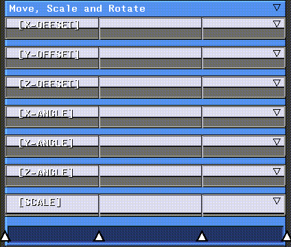
Figure 5.27 Move, Scale and Rotate operation automatically adds the subchannels required for the operation
2. (SHIFT-M) on the second marker in the marker track.
- Labels appear in each of the curve channels, showing the value of the curve at that cue. All cues tied to that marker are highlighted and labels appear in each curve channel, showing the value of that cue at that point in time.
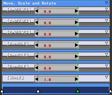
Figure 5.28 Create linked cues with the marker track
3. (DRAG-M) across the label for a curve to update the object's position interactively.
- Dragging back and forth over the channel changes the value of the cue, and updates the object interactively. (DRAG-L) updates the value in the cue, but doesn't update the object in the N-Geometry window until you let up on the mouse.
Table 5.68 Move, Scale, and Rotate parameters
|
Parameter
|
Dynamic?
|
Description
|
|---|
|
Object
|
No
|
The object to be transformed.
|
|
X, Y, and Z Offset
|
Yes
|
Offset value (in global units) for the object along the x, y, and z axes.
|
|
X, Y, and Z Angle
|
Yes
|
Rotation angle for the object in the x, y, and z axes.
|
|
Scale
|
Yes
|
Scaling factor for the object.
|
Translation
The translation operations below move an object based on its transformation matrix.
Axis Move
Moves an object along a specified axis.
Move to Object
Moves two objects toward each other. Note that this operation is actually moving the object centers toward each other. Typically, this operation occurs in a channel in the script after the transformation matrix for both objects have been initialized.
For example, you may want a bouncing ball to land on the roof of a car passing by; in such a script, the transformation matrix for both the car and the ball will usually have been initialized earlier on. This operation is typically used as a layered action in addition to the main actions being performed on two objects.
X Move
Move an object along the X axis.
Moves an object along the specified X axis.
XYZ Move [Linked]
Move an object to the specified position (or positions) using cues linked to a marker track to create keyframes. For more information on linking cues to markers, see the section "Move, Scale and Rotate [Linked]," on page 5-56.
Y Move
Moves the selected object along the specified Y axis. See the section "X Move," on page 5-59.
Z Move
Moves the selected object along the specified Z axis. See the section "X Move," on page 5-59.
Visibility
Controls whether objects are visible in the N-Geometry scene.
Make Invisible
Makes the selected object invisible.
Make Visible
Makes the selected object visible.
Set Visibility
Another way to turn the visibility of the selected object.
Paint Operations
The Paint Operations module contains operations that perform functions found in N-Paint.
Canvas Operations
The Canvas Operations class performs operations that affect the entire canvas (the workspace for the current image).
Composite Images
Composites images from two sources onto one another.
- Note. The two images being composited should be of the same size. In particular, if you save an image to the canvas-backup, then load a different image onto the canvas that is a different size, the contents of the canvas-backup are lost (since this is automatically update to match the size of the new image).
Erase Canvas
Paints over the entire canvas using the specified color.
If you want to change the color used to paint the canvas over the length of the script, make color a dynamic value, then (CLICK-M) on the curve channel. The Edit Curve properties menu lets you define the start and end colors for the animation.
(CLICK-L) on the color box next to either the Start Value or End Value to select a different color; a color palette appears; (CLICK-L) on the Edit button to modify the value of a color with sliders:
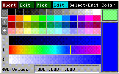
Figure 5.29 Color palette
If you insert additional cues into the curve channel, (CLICK-M) on the cue to bring up the color palette and change the color at that cue.
Choosing colors from a palette is described in more detail in the N-Paint Reference Guide.
Erase Matte
This operation is identical to the Erase Canvas operation, except that the destination is the matte channel rather than the canvas itself.
Working with the matte channel is described in more detail in the N-Paint Reference Guide.
Load Canvas from File
Loads the specified image file into the canvas. This can be animated to load an entire sequence of images.
Table 5.79 Load Canvas from File parameters
|
Parameter
|
Dynamic?
|
Description
|
|---|
|
Directory
|
No
|
The directory from which the image is loaded.
|
|
Filename
|
No
|
The name and format of the images being copied; the filename is used to determine which files are to be copied. The default filename,
"from-0001.tif" has four parts to it:
from is the base file name
- is the character that separates the base file name from the index number. This may be either a dash or a period.
0001 indicates the amount of padding used in the index (images are named 0001, 0002, etc.)
.tif is the extension part of the filename. This determines the format of the image (tif, rgb, rgba, sgi, or tpx).
|
|
Increment
|
No
|
An increment used when loading files. If the files are indexed, a new image is loaded each frame.
An increment of 1 loads images in sequence, an increment of 2 loads every other image, and an increment of 5 would load every 5th image. An increment of 0 loads only the specified image.
|
Load Canvas from Image
Loads an image currently in memory into the canvas.
Reverse Matte
Reverses the matte channel for the canvas (the current image).
Save Canvas to File
Saves the image currently on the canvas to file.
Table 5.81 Save Canvas to File parameters
|
Parameter
|
Dynamic?
|
Description
|
|---|
|
Directory
|
No
|
The directory to which the image is saved.
|
|
File Name
|
No
|
The name and format of the images being saved; the filename is used to determine which files are to be copied. The default filename,
"from-0001.tif" has four parts to it:
from is the base file name
- is the character that separates the base file name from the index number. This may be either a dash or a period.
0001 indicates the amount of padding used in the index (images are named 0001, 0002, etc.)
.tif is the extension part of the filename. This determines the format of the image (tif, rgb, rgba, sgi, or tpx).
|
|
Increment
|
No
|
An increment used when loading files. If the files are indexed, a new image is loaded each frame.
An increment of 1 loads images in sequence, an increment of 2 loads every other image, and an increment of 5 would load every 5th image. An increment of 0 loads only the specified image.
|
|
Bits per component
|
No
|
The depth for each component in the image (either 8 or 16).
|
Save Canvas to Image
Saves the image currently on the canvas to a named image.
Coloring
The Coloring operation class applies ink to a part or all of the canvas.
Four Color Gradient
Applies a four color gradient to the specified area of the canvas (or the entire canvas).
Table 5.83 Four Color Gradient parameters
|
Parameter
|
Dynamic?
|
Description
|
|---|
|
Upper Left
|
Can be
|
The color in the upper left corner of the shape.
|
|
Upper Right
|
Can be
|
The color in the upper right corner of the shape.
|
|
Lower Right
|
Can be
|
The color in the lower right corner of the shape
|
|
Lower Left
|
Can be
|
The color in the lower left corner of the shape.
|
|
Shape
|
No
|
The area in which the ink is to be applied; either a shape or the entire canvas.
|
|
Opacity
|
Can be
|
The opacity of the ink applied to the specified shape.
|
|
Matte
|
No
|
Sets the mode for the matte: Default, Off, Add, Use or Open. See the N-Paint Reference Guide for more information on these modes.
|
|
Mix Mode
|
No
|
Sets the default mix mode for the operation: Cover, Additive, Subtractive, PixelAdd, PixelSub. See the N-Paint Reference Guide for more information on these modes.
|
|
Components
|
No
|
Choose the components into which the gradient is to be applied: RGBA, Red, Green, Blue, Alpha, Intensity, Hue, Saturation, or Hue+Saturation.
|
Single Color
Applies a single color ink to the specified area of the canvas (or the entire canvas).
Table 5.84 Single Color parameters
|
Parameter
|
Dynamic?
|
Description
|
|---|
|
Color
|
Can be
|
The color to be applied to the specified shape.
|
|
Shape
|
No
|
The area in which the ink is to be applied; either a shape or the entire canvas.
|
|
Opacity
|
Can be
|
The opacity of the ink applied to the specified shape.
|
|
Matte
|
No
|
Sets the mode for the matte: Default, Off, Add, Use or Open. See the N-Paint Reference Guide for more information on these modes.
|
|
Mix Mode
|
No
|
Sets the default mix mode for the operation: Cover, Additive, Subtractive, PixelAdd, PixelSub. See the N-Paint Reference Guide for more information on these modes.
|
|
Components
|
No
|
Choose the components into which the ink is to be applied: RGBA, Red, Green, Blue, Alpha, Intensity, Hue, Saturation, or Hue+Saturation.
|
Two Color Gradient
Applies a two color gradient to the specified area of the canvas (or the entire canvas).
Table 5.85 Two Color Gradient parameters
|
Parameter
|
Dynamic?
|
Description
|
|---|
|
Color 1
|
Can be
|
The color used at the beginning of the gradient.
|
|
Color 2
|
Can be
|
The color used at the end of the gradient.
|
|
Direction
|
No
|
The direction the gradient should follow:
Vert creates the gradient from top to bottom.
Horiz creates the gradient from left to right.
Rad creates a radial gradient (from the center of the shape to the outer perimeter.
Ang lets you specify an angle in the shape at which the gradient is to begin; the color changes in a clock-wise direction around the shape.
|
|
Shape
|
No
|
The area in which the ink is to be applied; either a shape or the entire canvas.
|
|
Opacity
|
Can be
|
The opacity of the ink applied to the specified shape.
|
|
Matte
|
No
|
Sets the mode for the matte: Default, Off, Add, Use or Open. See the N-Paint Reference Guide for more information on these modes.
|
|
Mix Mode
|
No
|
Sets the default mix mode for the operation: Cover, Additive, Subtractive, PixelAdd, PixelSub. See the N-Paint Reference Guide for more information on these modes.
|
|
Components
|
No
|
Choose the components into which the ink is to be applied: RGBA, Red, Green, Blue, Alpha, Intensity, Hue, Saturation, or Hue+Saturation.
|
Copy Image
Copies, warps, or stretches one image into another shape or onto the canvas.
Copy Image
Copies pixels from another part of the image (or from a different image) into the area specified in shape.
Table 5.86 Copy Image parameters
|
Parameter
|
Dynamic?
|
Description
|
|---|
|
Image
|
No
|
The image in memory to be copied: Canvas to copy from another part of the canvas, Canvas-Backup to copy from the backup, or specify another image in memory.
|
|
X Offset
|
Can be
|
The horizontal offset for the copy.
|
|
Y Offset
|
Can be
|
The vertical offset for the copy.
|
|
Fixed
|
No
|
Specifies how the offset is calculated.
Yes copies from the corresponding area of the source image when drawing on the current canvas. If you draw a rectangle whose upper left corner is at 50, 50, the rectangular portion of the source image starting at 50, 50 is copied into the destination image.
No fills the portion of the source image starting at 0, 0 (the upper left corner.
|
|
Matte
|
No
|
If set to Yes, copies only the area under the matte of the source image onto the destination image (very useful as a compositing tool).
|
|
Shape
|
No
|
The area in which the ink is to be applied; either a shape or the entire canvas.
|
|
Opacity
|
Can be
|
The opacity of the ink applied to the specified shape.
|
|
Matte
|
No
|
Sets the mode for the matte: Default, Off, Add, Use or Open. See the N-Paint Reference Guide for more information on these modes.
|
|
Mix Mode
|
No
|
Sets the default mix mode for the operation: Cover, Additive, Subtractive, PixelAdd, PixelSub. See the N-Paint Reference Guide for more information on these modes.
|
|
Components
|
No
|
Choose the components into which the ink is to be applied: RGBA, Red, Green, Blue, Alpha, Intensity, Hue, Saturation, or Hue+Saturation.
|
Scale Image
Copies the entire specified image into the specified shape (or the entire canvas).
Table 5.87 Scale Image parameters
|
Parameter
|
Dynamic?
|
Description
|
|---|
|
Image
|
No
|
The image to be scaled (and copied) into the shape (or canvas).
|
|
Matte
|
No
|
If set to Yes, copies only the area under the matte of the source image onto the canvas (very useful as a compositing tool).
|
|
Shape
|
No
|
The area in which the ink is to be applied; either a shape or the entire canvas.
|
|
Opacity
|
Can be
|
The opacity of the ink applied to the specified shape.
|
|
Matte
|
No
|
Sets the mode for the matte: Default, Off, Add, Use or Open. See the N-Paint Reference Guide for more information on these modes.
|
|
Mix Mode
|
No
|
Sets the default mix mode for the operation: Cover, Additive, Subtractive, PixelAdd, PixelSub. See the N-Paint Reference Guide for more information on these modes.
|
|
Components
|
No
|
Choose the components into which the ink is to be applied: RGBA, Red, Green, Blue, Alpha, Intensity, Hue, Saturation, or Hue+Saturation.
|
Warp Image
Copies the selected image, or the entire canvas into the specified shape by stretching its edges to match the four corners of the rectangle.
Table 5.88 Warp Image parameters
|
Parameter
|
Dynamic?
|
Description
|
|---|
|
Image
|
No
|
The image to be warped.
|
|
Matte
|
No
|
If set to Yes, warps only the area under the matte of the source
image onto the destination image.
|
|
Shape
|
No
|
The area in which the ink is to be applied; either a shape or the entire canvas.
|
|
Opacity
|
Can be
|
The opacity of the ink applied to the specified shape.
|
|
Matte
|
No
|
Sets the mode for the matte: Default, Off, Add, Use or Open. See the N-Paint Reference Guide for more information on these modes.
|
|
Mix Mode
|
No
|
Sets the default mix mode for the operation: Cover, Additive, Subtractive, PixelAdd, PixelSub. See the N-Paint Reference Guide for more information on these modes.
|
|
Components
|
No
|
Choose the components into which the ink is to be applied: RGBA, Red, Green, Blue, Alpha, Intensity, Hue, Saturation, or Hue+Saturation.
|
Create Matte
Creates an alpha channel based on either an edge detection filter or on a chroma key pulled from the image.
Chroma Key
In N-Paint, the chroma key ink can be used to build a matte based on either RGB or IHS components of an image. It can be used to build a matte that lets you protect part or parts of an image based on their particular color or IHS characteristics.
For more information on creating a Chroma Key, see the N-Paint Reference Guide.
Table 5.89 Chroma Key parameters
|
Parameter
|
Dynamic?
|
Description
|
|---|
|
Test
|
No
|
Select whether to pull the matte based on the RGB or IHS values of the image.
|
|
Components
|
No
|
For IHS only, select the components with which to pull the matte: Intensity, Hue, or Saturation, or any combination.
|
|
Invert
|
No
|
Yes inverts the matte; a matte is created over those areas of the image that don't match the search criteria.
|
|
Color
|
Can be
|
The basic color to search for when pulling the matte.
|
|
Hard
|
Can be
|
A value between 0 and 1, which specifies the relative amount of the image given a 100% matte when compared to the test color. A value of 0 selects only pixels that match the test exactly, a value of .5 would select half of the pixels in the image, and a value of 1 would select all pixels.
|
|
Soft
|
Can be
|
A value between 0 and 1 that specifies the relative softness around the edge of the generated matte. A higher value produces a softer edge on the matte. A value of 0 would produce no softness, and a value of 1 would select the entire image.
|
|
Shape
|
No
|
The area in which the ink is to be applied; either a shape or the entire canvas.
|
|
Opacity
|
Can be
|
The opacity of the ink applied to the specified shape.
|
|
Matte
|
No
|
Sets the mode for the matte: Default, Off, Add, Use or Open. See the N-Paint Reference Guide for more information on these modes.
|
|
Mix Mode
|
No
|
Sets the default mix mode for the operation: Cover, Additive, Subtractive, PixelAdd, PixelSub. See the N-Paint Reference Guide for more information on these modes.
|
|
Components
|
No
|
Choose the components into which the ink is to be applied: RGBA, Red, Green, Blue, Alpha, Intensity, Hue, Saturation, or Hue+Saturation.
|
Edge Key
The edge key ink creates a high contrast matte along areas of high contrast (edges) in an image.
Table 5.90 Edge Key parameters
|
Parameter
|
Dynamic?
|
Description
|
|---|
|
Test Channel
|
No
|
Select whether to pull the matte based on the RGB or alpha values of the image.
|
|
Invert
|
No
|
Yes inverts the matte; a matte is created over those areas of the image that don't match the search criteria.
|
|
Shape
|
No
|
The area in which the ink is to be applied; either a shape or the entire canvas.
|
|
Opacity
|
Can be
|
The opacity of the ink applied to the specified shape.
|
|
Matte
|
No
|
Sets the mode for the matte: Default, Off, Add, Use or Open. See the N-Paint Reference Guide for more information on these modes.
|
|
Mix Mode
|
No
|
Sets the default mix mode for the operation: Cover, Additive, Subtractive, PixelAdd, PixelSub. See the N-Paint Reference Guide for more information on these modes.
|
|
Components
|
No
|
Choose the components into which the ink is to be applied: RGBA, Red, Green, Blue, Alpha, Intensity, Hue, Saturation, or Hue+Saturation.
|
Filtering
Applies the selected filtering effect to the selected area or to the entire image.
Blur
Blurs or "diffuses" the selected shape or the entire canvas.
Table 5.91 Blur parameters
|
Parameter
|
Dynamic?
|
Description
|
|---|
|
Iterations
|
Can be
|
The number of times the blur ink is applied to the selected area.
|
|
Size
|
No
|
3x3 blurs the image by averaging each pixel with its immediate neighbors (using a 3x3 grid.
7x7 blurs the image using three pixels on each side of the current pixel (using a 7x7 grid). This filter blurs the image even more than the 3x3 grid.
|
|
Shape
|
No
|
The area in which the ink is to be applied; either a shape or the entire canvas.
|
|
Opacity
|
Can be
|
The opacity of the ink applied to the specified shape.
|
|
Matte
|
No
|
Sets the mode for the matte: Default, Off, Add, Use or Open. See the N-Paint Reference Guide for more information on these modes.
|
|
Mix Mode
|
No
|
Sets the default mix mode for the operation: Cover, Additive, Subtractive, PixelAdd, PixelSub. See the N-Paint Reference Guide for more information on these modes.
|
|
Components
|
No
|
Choose the components into which the ink is to be applied: RGBA, Red, Green, Blue, Alpha, Intensity, Hue, Saturation, or Hue+Saturation.
|
Distort
Applies a distortion map to the selected shape or to the entire canvas. For a complete description of how to build and use distortion map, see the N-Paint Reference Guide.
Table 5.92 Distort parameters
|
Parameter
|
Dynamic?
|
Description
|
|---|
|
Map
|
No
|
Is the distorted map.
|
|
Base
|
No
|
Is the base map.
|
|
Amount
|
Can be
|
The amount to distort the image between the two maps (e.g., .5 would distort the image halfway).
|
|
Shape
|
No
|
The area in which the ink is to be applied; either a shape or the entire canvas.
|
|
Opacity
|
Can be
|
The opacity of the ink applied to the specified shape.
|
|
Matte
|
No
|
Sets the mode for the matte: Default, Off, Add, Use or Open. See the N-Paint Reference Guide for more information on these modes.
|
|
Mix Mode
|
No
|
Sets the default mix mode for the operation: Cover, Additive, Subtractive, PixelAdd, PixelSub. See the N-Paint Reference Guide for more information on these modes.
|
|
Components
|
No
|
Choose the components into which the ink is to be applied: RGBA, Red, Green, Blue, Alpha, Intensity, Hue, Saturation, or Hue+Saturation.
|
Expand
For the affected area, the value of every pixel is set to its lightest neighboring pixel. (You could use this ink to clean dirt specks from an image that had a lower intensity than the rest of the image.)
Table 5.93 Expand parameters
|
Parameter
|
Dynamic?
|
Description
|
|---|
|
Iterations
|
Can be
|
The number of times to repeat the application of the ink on the selected area (or the entire canvas).
|
|
Shape
|
No
|
The area in which the ink is to be applied; either a shape or the entire canvas.
|
|
Opacity
|
Can be
|
The opacity of the ink applied to the specified shape.
|
|
Matte
|
No
|
Sets the mode for the matte: Default, Off, Add, Use or Open. See the N-Paint Reference Guide for more information on these modes.
|
|
Mix Mode
|
No
|
Sets the default mix mode for the operation: Cover, Additive, Subtractive, PixelAdd, PixelSub. See the N-Paint Reference Guide for more information on these modes.
|
|
Components
|
No
|
Choose the components into which the ink is to be applied: RGBA, Red, Green, Blue, Alpha, Intensity, Hue, Saturation, or Hue+Saturation.
|
Mosaic
"Pixelates" the affected area (the same affect that occurs when repeatedly zooming in on an image). The new cell size is determined by the X and Y values specified.
Table 5.94 Mosaic parameters
|
Parameter
|
Dynamic?
|
Description
|
|---|
|
X Duplication
|
Can be
|
The width of the repeating cells.
|
|
Y Duplication
|
Can be
|
The height of the repeating cells.
|
|
Shape
|
No
|
The area in which the ink is to be applied; either a shape or the entire canvas.
|
|
Opacity
|
Can be
|
The opacity of the ink applied to the specified shape.
|
|
Matte
|
No
|
Sets the mode for the matte: Default, Off, Add, Use or Open. See the N-Paint Reference Guide for more information on these modes.
|
|
Mix Mode
|
No
|
Sets the default mix mode for the operation: Cover, Additive, Subtractive, PixelAdd, PixelSub. See the N-Paint Reference Guide for more information on these modes.
|
|
Components
|
No
|
Choose the components into which the ink is to be applied: RGBA, Red, Green, Blue, Alpha, Intensity, Hue, Saturation, or Hue+Saturation.
|
Noise Filter
A filter ink designed to remove noise (specks) from an image. Noise is eliminated by changing the value of the "offending" pixel with the median value of surrounding pixels.
Table 5.95 Noise Filter parameters
|
Parameter
|
Dynamic?
|
Description
|
|---|
|
Dark
|
Can be
|
The percentage darker a pixel must differ from its neighbors to be considered "noise."
|
|
Light
|
Can be
|
The percentage lighter a pixel must differ from its neighbors to be considered "noise."
|
|
Shape
|
No
|
The area in which the ink is to be applied; either a shape or the entire canvas.
|
|
Opacity
|
Can be
|
The opacity of the ink applied to the specified shape.
|
|
Matte
|
No
|
Sets the mode for the matte: Default, Off, Add, Use or Open. See the N-Paint Reference Guide for more information on these modes.
|
|
Mix Mode
|
No
|
Sets the default mix mode for the operation: Cover, Additive, Subtractive, PixelAdd, PixelSub. See the N-Paint Reference Guide for more information on these modes.
|
|
Components
|
No
|
Choose the components into which the ink is to be applied: RGBA, Red, Green, Blue, Alpha, Intensity, Hue, Saturation, or Hue+Saturation.
|
Scatter
Creates a "streaking" or scattering effect, depending on whether one or both parameters are used.
Table 5.96 Scatter parameters
|
Parameter
|
Dynamic?
|
Description
|
|---|
|
Horizontal
|
Can be
|
The maximum horizontal distance that pixels are scattered. Use a higher value for more scatter. If you use only the horizontal component, images appear to have streaking from left to right.
|
|
Vertical
|
Can be
|
The maximum vertical distance that pixels are scattered. Use a higher value for more scatter. If you use only the horizontal component, images appear to have streaking from top to bottom.
|
|
Shape
|
No
|
The area in which the ink is to be applied; either a shape or the entire canvas.
|
|
Opacity
|
Can be
|
The opacity of the ink applied to the specified shape.
|
|
Matte
|
No
|
Sets the mode for the matte: Default, Off, Add, Use or Open. See the N-Paint Reference Guide for more information on these modes.
|
|
Mix Mode
|
No
|
Sets the default mix mode for the operation: Cover, Additive, Subtractive, PixelAdd, PixelSub. See the N-Paint Reference Guide for more information on these modes.
|
|
Components
|
No
|
Choose the components into which the ink is to be applied: RGBA, Red, Green, Blue, Alpha, Intensity, Hue, Saturation, or Hue+Saturation.
|
Sharpen
Sharpens the specified area (or the entire canvas).
Table 5.97 Sharpen parameters
|
Parameter
|
Dynamic?
|
Description
|
|---|
|
Amount
|
Can be
|
The sharpness of the filter (a value of 0 does no sharpening; the maximum value is 1.)
|
|
Shape
|
No
|
The area in which the ink is to be applied; either a shape or the entire canvas.
|
|
Opacity
|
Can be
|
The opacity of the ink applied to the specified shape.
|
|
Matte
|
No
|
Sets the mode for the matte: Default, Off, Add, Use or Open. See the N-Paint Reference Guide for more information on these modes.
|
|
Mix Mode
|
No
|
Sets the default mix mode for the operation: Cover, Additive, Subtractive, PixelAdd, PixelSub. See the N-Paint Reference Guide for more information on these modes.
|
|
Components
|
No
|
Choose the components into which the ink is to be applied: RGBA, Red, Green, Blue, Alpha, Intensity, Hue, Saturation, or Hue+Saturation.
|
Shrink
For the affected area, the value of every pixel is set to its darkest neighboring pixel. (You could use this ink to clean dirt specks from an image that had a higher intensity than the rest of the image.)
Table 5.98 Shrink parameters
|
Parameter
|
Dynamic?
|
Description
|
|---|
|
Iterations
|
Can be
|
The number of times to repeat the application of the ink on the selected area (or the entire canvas).
|
|
Shape
|
No
|
The area in which the ink is to be applied; either a shape or the entire canvas.
|
|
Opacity
|
Can be
|
The opacity of the ink applied to the specified shape.
|
|
Matte
|
No
|
Sets the mode for the matte: Default, Off, Add, Use or Open. See the N-Paint Reference Guide for more information on these modes.
|
|
Mix Mode
|
No
|
Sets the default mix mode for the operation: Cover, Additive, Subtractive, PixelAdd, PixelSub. See the N-Paint Reference Guide for more information on these modes.
|
|
Components
|
No
|
Choose the components into which the ink is to be applied: RGBA, Red, Green, Blue, Alpha, Intensity, Hue, Saturation, or Hue+Saturation.
|
Pixel Moving
These inks affect the selected area of the canvas, as their operation class implies, by moving pixels.
Flip
Flips the selected area (or the entire canvas) in the specified direction. This would be useful for images saved in non-standard formats (which sometimes read in upside-down) or images that were scanned incorrectly (e.g., a slide that was scanned from the wrong side).
Table 5.99 Flip parameters
|
Parameter
|
Dynamic?
|
Description
|
|---|
|
Direction
|
No
|
Vert flips the image from top to bottom.
Horiz flips the image from side to side.
|
|
Shape
|
No
|
The area in which the ink is to be applied; either a shape or the entire canvas.
|
|
Opacity
|
Can be
|
The opacity of the ink applied to the specified shape.
|
|
Matte
|
No
|
Sets the mode for the matte: Default, Off, Add, Use or Open. See the N-Paint Reference Guide for more information on these modes.
|
|
Mix Mode
|
No
|
Sets the default mix mode for the operation: Cover, Additive, Subtractive, PixelAdd, PixelSub. See the N-Paint Reference Guide for more information on these modes.
|
|
Components
|
No
|
Choose the components into which the ink is to be applied: RGBA, Red, Green, Blue, Alpha, Intensity, Hue, Saturation, or Hue+Saturation.
|
Magnify
Magnifies the pixels under the selected area, as if they were being viewed under a magnifying glass.
Table 5.100 Magnify parameters
|
Parameter
|
Dynamic?
|
Description
|
|---|
|
Scale
|
Can be
|
The factor by which the size of each pixel is modified.
|
|
Shape
|
No
|
The area in which the ink is to be applied; either a shape or the entire canvas.
|
|
Opacity
|
Can be
|
The opacity of the ink applied to the specified shape.
|
|
Matte
|
No
|
Sets the mode for the matte: Default, Off, Add, Use or Open. See the N-Paint Reference Guide for more information on these modes.
|
|
Mix Mode
|
No
|
Sets the default mix mode for the operation: Cover, Additive, Subtractive, PixelAdd, PixelSub. See the N-Paint Reference Guide for more information on these modes.
|
|
Components
|
No
|
Choose the components into which the ink is to be applied: RGBA, Red, Green, Blue, Alpha, Intensity, Hue, Saturation, or Hue+Saturation.
|
Mirror
Creates a "mirror" effect in the area to which the ink is applied (or to the entire canvas).
Table 5.101 Mirror parameters
|
Parameter
|
Dynamic?
|
Description
|
|---|
|
Direction
|
No
|
Vert mirrors the top half of the area onto the bottom half of the area.
Horiz mirrors the left half of the area onto the right half of the area.
|
|
Shape
|
No
|
The area in which the ink is to be applied; either a shape or the entire canvas.
|
|
Opacity
|
Yes
|
The opacity of the ink applied to the specified shape.
|
|
Matte
|
No
|
Sets the mode for the matte: Default, Off, Add, Use or Open. See the N-Paint Reference Guide for more information on these modes.
|
|
Mix Mode
|
No
|
Sets the default mix mode for the operation: Cover, Additive, Subtractive, PixelAdd, PixelSub. See the N-Paint Reference Guide for more information on these modes.
|
|
Components
|
No
|
Choose the components into which the ink is to be applied: RGBA, Red, Green, Blue, Alpha, Intensity, Hue, Saturation, or Hue+Saturation.
|
Shift
Shifts the selected area (or the entire canvas) either horizontally or vertically a number of pixels. (The amount the canvas is shifted can be either static or dynamic.)
Table 5.102 Shift parameters
|
Parameter
|
Dynamic?
|
Description
|
|---|
|
Horizontal
|
Can be
|
Shifts the area right or left. A positive value shift the image to the left, negative to the right. This value can be local or dynamic.
|
|
Vertical
|
Can be
|
Shifts the area up or down. A positive value shifts the image up, a negative value down. This value can be local or dynamic.
|
|
Shape
|
No
|
The area in which the ink is to be applied; either a shape or the entire canvas.
|
|
Opacity
|
Can be
|
The opacity of the ink applied to the specified shape.
|
|
Matte
|
No
|
Sets the mode for the matte: Default, Off, Add, Use or Open. See the N-Paint Reference Guide for more information on these modes.
|
|
Mix Mode
|
No
|
Sets the default mix mode for the operation: Cover, Additive, Subtractive, PixelAdd, PixelSub. See the N-Paint Reference Guide for more information on these modes.
|
|
Components
|
No
|
Choose the components into which the ink is to be applied: RGBA, Red, Green, Blue, Alpha, Intensity, Hue, Saturation, or Hue+Saturation.
|
Recoloring
The inks in the Recoloring Operation class change the value of individual pixels.
Equalize
Often, a scanned or frame-grabbed image uses only a fraction of the colors actually available in the format. The Equalize command spreads the colors of the selected area (or the entire canvas) over the entire available spectrum. The effect is most visible on images that appear "dull" or "faded;" such images appear to "pop" when equalized.
Table 5.103 Equalize parameters
|
Parameter
|
Dynamic?
|
Description
|
|---|
|
Low
|
Can be
|
The lower intensity value of pixels to be included in the equalization process. This is a threshold; any pixels below this value are changed to black.
|
|
High
|
Can be
|
The upper intensity value of pixels to be included in the equalization
process. This is a threshold; any pixels above this value are changed
to white.
|
|
Shape
|
No
|
The area in which the ink is to be applied; either a shape or the entire canvas.
|
|
Opacity
|
Can be
|
The opacity of the ink applied to the specified shape.
|
|
Matte
|
No
|
Sets the mode for the matte: Default, Off, Add, Use or Open. See the N-Paint Reference Guide for more information on these modes.
|
|
Mix Mode
|
No
|
Sets the default mix mode for the operation: Cover, Additive, Subtractive, PixelAdd, PixelSub. See the N-Paint Reference Guide for more information on these modes.
|
|
Components
|
No
|
Choose the components into which the ink is to be applied: RGBA, Red, Green, Blue, Alpha, Intensity, Hue, Saturation, or Hue+Saturation.
|
IHS Recolor
Recolor the selected area (or the entire canvas) based on Intensity, Hue, or Saturation levels.
Table 5.104 IHS Recolor parameters
|
Parameter
|
Dynamic?
|
Description
|
|---|
|
Component
|
No
|
Specifies the component (Intensity, Hue, Saturation, or Hue+Saturation) to be modified by this operation.
|
|
Operation
|
No
|
Set lets you specify a value for the component (using the Color field below).
Shift lets you shift the specified component up or down by the specified Amount.
Scale lets you specify a factor by which you want to move the component up or down.
|
|
Color
|
Can be
|
For use with the Set operation only. Supplies the color from which the specified component is taken (and applied to the specified area).
|
|
Amount
|
Can be
|
The value used when applying the operation specified above (used in Shift and Scale mode).
|
|
Shape
|
No
|
The area in which the ink is to be applied; either a shape or the entire canvas.
|
|
Opacity
|
No
|
The opacity of the ink applied to the specified shape.
|
|
Matte
|
No
|
Sets the mode for the matte: Default, Off, Add, Use or Open. See the N-Paint Reference Guide for more information on these modes.
|
|
Mix Mode
|
No
|
Sets the default mix mode for the operation: Cover, Additive, Subtractive, PixelAdd, PixelSub. See the N-Paint Reference Guide for more information on these modes.
|
|
Components
|
No
|
Choose the components into which the ink is to be applied: RGBA, Red, Green, Blue, Alpha, Intensity, Hue, Saturation, or Hue+Saturation.
|
Posterize
Posterization is the "banding" effect sometimes seen on images represented with fewer colors than are required for a continuous tone image.
Table 5.105 Posterize parameters
|
Parameter
|
Dynamic?
|
Description
|
|---|
|
Segments
|
Can be
|
The number of colors to break the specified area (or the entire canvas) into. A value of 256 leaves the image unaffected.
|
|
Shape
|
No
|
The area in which the ink is to be applied; either a shape or the entire canvas.
|
|
Opacity
|
Can be
|
The opacity of the ink applied to the specified shape.
|
|
Matte
|
No
|
Sets the mode for the matte: Default, Off, Add, Use or Open. See the N-Paint Reference Guide for more information on these modes.
|
|
Mix Mode
|
No
|
Sets the default mix mode for the operation: Cover, Additive, Subtractive, PixelAdd, PixelSub. See the N-Paint Reference Guide for more information on these modes.
|
|
Components
|
No
|
Choose the components into which the ink is to be applied: RGBA, Red, Green, Blue, Alpha, Intensity, Hue, Saturation, or Hue+Saturation.
|
Randomize
Adds a random amount of noise to the selected area (or to the entire canvas).
Table 5.106 Randomize parameters
|
Parameter
|
Dynamic?
|
Description
|
|---|
|
Amount
|
Can be
|
The amount of noise introduced (a higher number produces a more visible effect). A value of 0 produces no change, and the maximum value you can specify is 1.
|
|
Shape
|
No
|
The area in which the ink is to be applied; either a shape or the entire canvas.
|
|
Opacity
|
Can be
|
The opacity of the ink applied to the specified shape.
|
|
Matte
|
No
|
Sets the mode for the matte: Default, Off, Add, Use or Open. See the N-Paint Reference Guide for more information on these modes.
|
|
Mix Mode
|
No
|
Sets the default mix mode for the operation: Cover, Additive, Subtractive, PixelAdd, PixelSub. See the N-Paint Reference Guide for more information on these modes.
|
|
Components
|
No
|
Choose the components into which the ink is to be applied: RGBA, Red, Green, Blue, Alpha, Intensity, Hue, Saturation, or Hue+Saturation.
|
RGBA Recolor
Recolor the selected area (or the entire canvas) based on its RGB levels.
Table 5.107 RGBA Recolor parameters
|
Parameter
|
Dynamic?
|
Description
|
|---|
|
Operation
|
No
|
Set lets you specify a value for the component (using the Color field below).
Shift lets you shift the specified component up or down by the specified Amount.
Scale lets you specify a factor by which you want to move the component up or down.
Exponent exponentiates the value of the color. This is equivalent to setting the "gamma" of the selected area.
Cycle cycles the colors by putting them through a lookup table.
Invert creates a negative for the selected component when the ink is applied.
|
|
Component
|
No
|
The channels upon which the operation is to be performed.
|
|
Amount
|
Can be
|
The value used when applying the operation specified above.
|
|
Shape
|
No
|
The area in which the ink is to be applied; either a shape or the entire canvas.
|
|
Opacity
|
Can be
|
The opacity of the ink applied to the specified shape.
|
|
Matte
|
No
|
Sets the mode for the matte: Default, Off, Add, Use or Open. See the N-Paint Reference Guide for more information on these modes.
|
|
Mix Mode
|
No
|
Sets the default mix mode for the operation: Cover, Additive, Subtractive, PixelAdd, PixelSub. See the N-Paint Reference Guide for more information on these modes.
|
|
Components
|
No
|
Choose the components into which the ink is to be applied: RGBA, Red, Green, Blue, Alpha, Intensity, Hue, Saturation, or Hue+Saturation.
|
Swap Channels
Swaps the values of components in a selected area (or the entire canvas). This is particularly useful, for example, if you want to copy the red, green, or blue channel to or from the alpha channel (the matte), or if you have imported an image from another system whose channels are swapped.
Table 5.108 Swap Channels parameters
|
Parameter
|
Dynamic?
|
Description
|
|---|
|
Red Gets
|
No
|
Copies the value of the specified channel into the red channel.
|
|
Green Gets
|
No
|
Copies the value of the specified channel into the green channel.
|
|
Blue Gets
|
No
|
Copies the value of the specified channel into the blue channel.
|
|
Alpha Gets
|
No
|
Copies the value of the specified channel into the alpha channel.
|
|
Shape
|
No
|
The area in which the ink is to be applied; either a shape or the entire canvas.
|
|
Matte
|
No
|
Sets the mode for the matte: Default, Off, Add, Use or Open. See the N-Paint Reference Guide for more information on these modes.
|
|
Mix Mode
|
No
|
Sets the default mix mode for the operation: Cover, Additive, Subtractive, PixelAdd, PixelSub. See the N-Paint Reference Guide for more information on these modes.
|
|
Components
|
No
|
Choose the components into which the ink is to be applied: RGBA, Red, Green, Blue, Alpha, Intensity, Hue, Saturation, or Hue+Saturation.
|
Other Operations
Render
If you are using N-Dynamics in conjunction with the N-Render package, this operation lets you render your scenes.
Table 5.109 Render parameters
|
Parameter
|
Dynamic?
|
Render
|
GL Shade
|
|---|
|
Render Domain
|
No
|
Render renders the scene using the N-Render product, a high quality, photorealistic renderer.
Render to either the render window or the paint canvas.
|
GL Shade renders the scene using GL Shade, the built-in SGI hardware renderer.
Output to the N-Geometry window only.
|
|
Directory
|
No
|
The directory into which rendered images should be saved.
|
|
File Name
|
No
|
The filename under which rendered images are saved.
|
|
Output WIndow
|
No
|
Render renders the scene to the N-Render preview window.
Paint renders the scene to the N-Paint canvas.
|
|
|
Background
|
No
|
Clear renders the scene after clearing the target window.
Existing Image renders the scene over the image in the currently specified Output WIndow (essentially a composite mode).
|
|
|
Width
|
No
|
The width of the output image.
|
|
|
Height
|
No
|
The height of the output image.
|
|
|
Gamma
|
Can be
|
Gamma correction value, normally set to 1.0. Refer to the
N-Render Reference Guide for mor information on setting gamma.
|
|
|
Increment
|
No
|
|
The increment for rendered frames; a value of 1 renders every frame, 2 renders every other frame, 5 every fifth frame, etc.
|
|
Scale
|
No
|
|
Scales the output to the
N-Geometry window
|
|
Compute Matte?
|
No
|
Whether or not an alpha channel is computed for the rendered scene. An alpha channel is created under any object rendered, paying attention to the opacity of the object.
|
|
Save Render?
|
No
|
Whether or not an image file is saved in the Directory and File Name specified above.
|
|
Output Format
|
No
|
The format for the output image: SGI RGB, TIFF, or TPX.
|
|
Compress Image
|
No
|
If Yes, the UNIX compress command is applied to the output image.
|
|
Disable Redraw
|
No
|
|
When this is set to Yes, this disables N-Dynamics' automatic redrawing of the current N-Geometry window.
Because the scene is redrawn as soon as it is rendered, if you do not disable N-Dynamics' automatic redraw, the scene is drawn twice, which can slow down renders.
|
Attributes
Animate Attributes
Change the attributes in a material over time. The attributes that can be animated depend on which render domain is selected. To use this operation:
1. Choose the domain for which you wish to animate an attribute.
2. (CLICK-L) on the material you want to animate over time.
- (CLICK-L) on Attribute Name.
- Depending on the the domain selected, a number of different options are displayed. For example, if you are using the Render domain, the attributes that can be animated are grouped further into different attribute classes (shader, texture, bump, opacity, reflect, and refract).
- For most other domains, all of the attributes that can be animated appear on a single list.
3. To animate the attribute, edit the dynamic value for the operation ((CLICK-M) on the curve channel) and update the values for that channel.
Render Domain
Animatable attributes are divided into six classes: shader, texture, bump, opacity, reflect, and refract. For more information on any of the particular attributes, refer to the Attributes Editor & N-Render User's Guide.
GL Shade Domain
Animatable attributes include Diffuse Color, Shininess, Specular Color, Emission Color, and Opacity.
Sega Domain
Animatable attributes include Gouraud, Mode, and Diffuse Color.
Sony PSX Domain
Only Diffuse Color can be animated.
N64 Domain
Only Diffuse Color can be animated.
The values that must be specified to animate an attribute change depending on the nature of the attribute. When animating a color, for example, you can select the start and end color to animate between, while other values requiring a start and end value may prompt you to enter those values as a doublet (two pairs of numbers).
For a complete description of the parameters each parameter, refer to the N-Render Reference Guide.
[N-World Contents] [Book Contents] [Prev] [Next] [Index]
 Another fine product from Nichimen documentation!
Copyright © 1996, Nichimen Graphics Corporation. All rights
reserved.


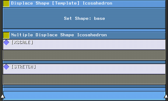


 Another fine product from Nichimen documentation!