[N-World Contents] [Book Contents] [Prev] [Next] [Index]
Tubes
This chapter describes a simple technique for building another
relatively low-polygon count environment in only a few steps using tubes.
New Techniques in this Chapter
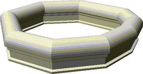
Earlier we learned how to build a dungeon environment; in this chapter we'll learn how to build a similar, but more detailed environment using N-Geometry's tube primitive.
The Improved Dungeon
In our earlier dungeon exercise, we built an environment by extruding a cube in several directions and creating tunnels by bridging from face to face.
In this tutorial, we'll use N-Geometry's tube to build a tunnel of irregular shape around a path that you define.
Sketching the Path Wire
A tube is a polyhedron created by sweeping a cross-section (defined by one wire) along a path (defined by another wire). There are three steps in building a tube:
Building the Path Wire
In this section, we'll build the path wire.
Try this:
1. (CLICK-L) on GeoMenus>File>New Object>Tube.
- The following menu appears:
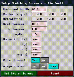
Figure 16.1 Specifying path parameters
- Each of the parameters on this menu is described in detail in the N-Geometry Reference Guide.
- For now, use the default parameters as described above.
2. (CLICK-L) on the Set Sketch Params button.
- Using the sketching tools you've learned in previous tutorials, create a loop path for your dungeon:
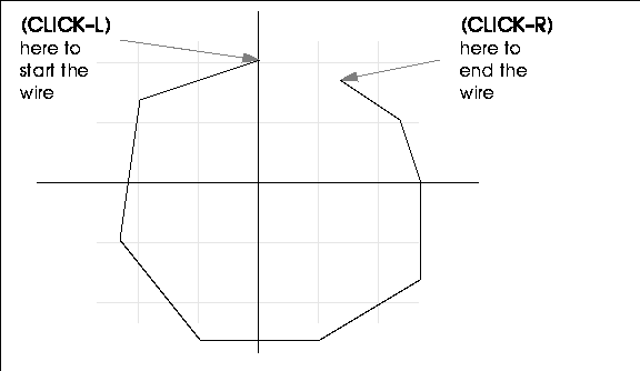
Figure 16.2 Starting the wire
3. (CLICK-L) on OK after you've completed the wire.
- The Select Tube Parameters menu appears:
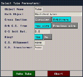
Figure 16.3 Specifying tube parameters
- Make the following changes to the defaults on this menu:
4. (CLICK-L) on the Make Tube button.
- The sketch editor appears again. This time, you're creating the cross-section that will be moved along the path wire to create the tube, so make sure to draw it at an appropriately smaller scale. Try something like this:
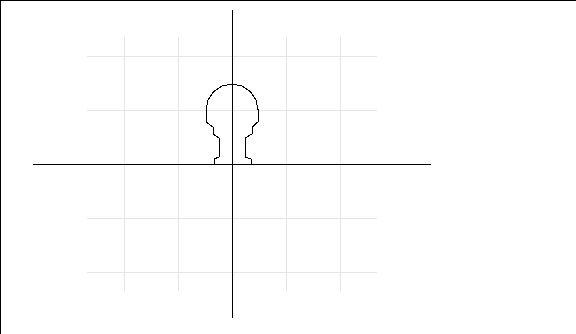
Figure 16.4 Creating the cross section
5. (CLICK-L) on OK after you've completed the wire.
- The completed tube appears in the N-Geometry window.

Figure 16.5 The generated tube
- The tube may be inside out, depending on which way you drew the cross section. If you turn on shading for the object and see the inside rather than the outside, the tube is inside out.
6. (CLICK-L) on bodies on the element sensitivity menu, then (SHIFT-L) on the generated tube.
7. (CLICK-L) on Evert.
- You can (CLICK-R) on GeoMenus>Object Display>Normals, then (CLICK-L) on Tube to display the normals of the faces on the generated tube if you want to see which way they're facing.

Figure 16.6 The everted tube, normals facing out
Fixing the Floor
Depending on how you completed the cross-section wire, you may have a floor that isn't completely flat; here's how to fix it.
8. Evert the tube so that the normals are pointing into the tube.
- Move the camera in so that you're pointing at a segment along the inner floor of the hallway:
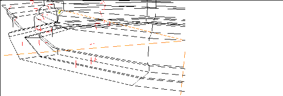
Figure 16.7 Normals facing in
- Notice that because the ending point on our wire didn't exactly match the starting point for the wire, extra faces were created; also, because we didn't use the grid to create our cross-section (even though you may have), the segments along the floor may not all be flat.
9. Move the camera in so that you're pointing toward the floor.
10. (SHIFT-L) on one of the segments.

Figure 16.8 Select a segment along the floor
11. (CLICK-L) on Select Edge Loop to collect the all the segments around the perimeter of the floor.
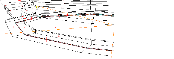
Figure 16.9 Select the edge loop for that segment
12. (SHIFT-L) on the collection, then (CLICK-L) on Dissolve.
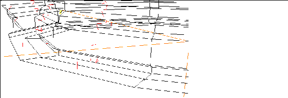
Figure 16.10 Dissolve the edge loop
Now zoom in even closer; dissolving the edge loop created a "step":

Figure 16.11 Resulting "step"
13. Select an edge like the one shown below:
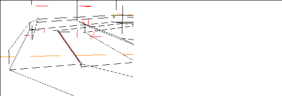
Figure 16.12 Select the edge shown
14. (SHIFT-L) on the segment, then (CLICK-L) on Select Edge Loop.
15. (SHIFT-L) on the collection, then (CLICK-L) on Select Elements.
- This selects the vertices on the selected segments.
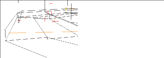
Figure 16.13 Select the vertices on the edge loop
16. (SHIFT-L) on the collection, then (CLICK-L) on Flatten.
17. (CLICK-L) on Y for the axis on which to flatten the selected points.
- N-Geometry goes into point-select mode. Pick one of the points on the bottom of the step:
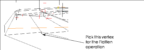
Figure 16.14 Select the vertices on the edge loop
- The floor should now look like this:

Figure 16.15 Tube with flattened floor
Now our floor at least appears to be correct; however, if you remember our discussion of "virtual clay" all the way back in Chapter 1, you'll remember that a model's surface is always maintained, which means that even if points become coincident, they don't lose their identity.
Try this:
18. (CLICK-L) on points on the element sensitivity menu.
19. (SHIFT-L) on one of the vertices on the floor, then (CLICK-L) on Move.
- You should see something like this:
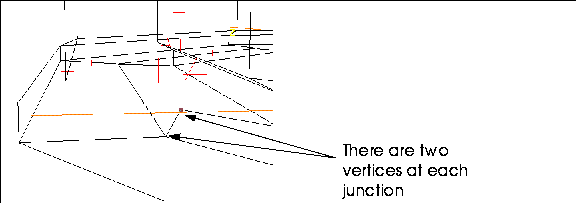
Figure 16.16 The two vertices still exist
20. (CLICK-R) to Abort the Move operation.
- (Press the "u" hot key to undo the move if you changed the point's position.)
21. (CLICK-L) on bodies on the element sensitivity menu.
22. (SHIFT-L) on the tube, then (CLICK-L) on Cull Elements>Isolated Vertices.
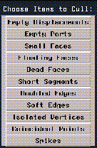
Figure 16.17 Cull Elements options
23. Now, move the point again:
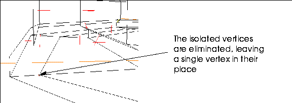
Figure 16.18 The isolated vertices are removed
- The isolated vertex has been removed.
24. (CLICK-L) on GeoMenus>Shading>Tube.
- The inside of the tube should look something like this:

Figure 16.19 Inside the shaded tube
Working with Normals
Use the Evert command to flip the normals so that they're pointing to the correct side:
If you look at your tube from the outside, your shaded tube should look something like this:

Figure 16.20 Outside the shaded tube
Save your Work
Make sure to use the GeoMenus>File>Save operation to save your work.
Congratulations!
You've now completed an entire environment based on two simple sketched wires.
[N-World Contents] [Book Contents] [Prev] [Next] [Index]
 Another fine product from Nichimen documentation!
Copyright © 1996, Nichimen Graphics Corporation. All rights
reserved.


 Another fine product from Nichimen documentation!