[N-World Contents] [Book Contents] [Prev] [Next] [Index]
Render Domains
A material can be used in one or more domains; each render domain has a different set of attributes that can be specified to take advantage of that domain. This chapter describes the attributes for the GL Shade and the Render domains. (Attributes for the various game domains is described in more detail in the appropriate Game Express manuals.)

GL Shade Domain
You can specify Shader and Texture map parameters for the GL Shade domain. The preferences you specify here are used as defaults if you do not make any changes to the material locally.
Setting GL Shade Preferences
To set GL Shade Preferences, (CLICK-L) on the GL Shade button, then (CLICK-L) on the Prefs button. The GL Shade defaults menu appears:

Figure 3.1 The GL Shade domain defaults menu
Map Directory
This is the default directory for texture maps.
After specifying a map directory, (CLICK-L) on one of the buttons at the bottom of the dialog box:
Shader Attributes (GL Shade)
To edit Shader attributes, (CLICK-L) on the Shader icon in the Material Parameters section of the Attributes Editor menu. The GL Shade shader attributes appear in the Attributes section of the Attributes Editor window:
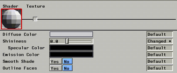
Figure 3.2 GL Shade shader attributes
Diffuse Color
Specifies the diffuse color of the object. Diffuse color is the color reflected by the object equally in all directions. (CLICK-L) on the field to reveal a Select Color dialog.
Shininess
This parameter controls the prominence of the specular highlight. A higher value produces a more prominent highlight, and a "shinier" look.
Specular Color
Sets the color of the specular highlight.
Emission Color
This color defines the darkest possible color of the surface.
Smooth Shade?
Selects the interpolation method used to render. Smooth shade creates a smoother transition between neighboring faces, giving the object an overall smoother appearance.
Outline Faces
Draws outlines around each face of the object being rendered.
Texture Parameters (GL Shade)
Texture parameters control texture maps you wish to include in your materials.
Texture Map
A texture map is an image which is projected onto an object. (CLICK-L) on this field to select an image map from among files in the default map directory.
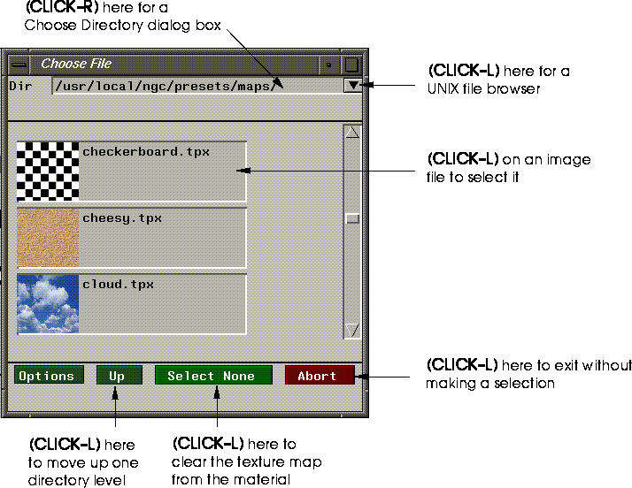
Figure 3.3 Select map file (shown here with icons on)
Render Domain (N-Render)
The Render domain is N·World's native render domain. N-Render, N·World's native renderer, includes expanded support for shader attributes like ray tracing, as well as more powerful image-mapping techniques.
Setting Render Domain Preferences
To set your N-Render defaults, (CLICK-L) on the Render domain button, then (CLICK-L) on the Prefs button. The following dialog box is displayed:
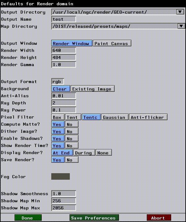
Figure 3.4 Setting N-Render defaults
Output Directory
The directory into which rendered image files are written. Intermediate render files are kept in this directory, which N-Render uses to build the final rendered image.
Output Name
The prefix for the render file.
Map Directory
The default directory for map image files. When specifying a map file for a texture, bump, or other type of map, this is the directory that is specified if you have not loaded a map from any other directory in this session.
Output Window
The destination window into which the current scene is rendered.
Render Width
The width of the rendered image (in pixels).
Render Height
The height of the rendered image (in pixels).
Render Gamma
The overall gamma correction value to be applied to the rendered scene. A lower value will produce a darker image. The default gamma value for the SGI is 1.0.
Output Format
The file format of the rendered image. (CLICK-L) on this field and choose a format from the pop-up menu:

Figure 3.5 Select output format pop-up menu
Background
Specifies what to do with the image currently in the Output Window:
Anti-Alias
Determines how much of the surrounding area to use when computing the color of each pixel. Higher values mean images are rendered more quickly at the expense of image quality.
Ray Depth
Determines how many ray bounces to calculate. A value of 1 results in essentially a scan line render (a single bounce). Higher values give a more pronounced ray tracing effect.
Ray Power
The minimum power at which a ray will bounce. A ray loses some value power each time it bounces or passes through a semi-transparent object. A lower value will allow the ray to bounce more times.
Ray traced images have a more natural look and feel to them; the ability of a ray tracing renderer to simulate the bouncing of light found in real-world environments makes it simple to create lifelike images like the one shown in
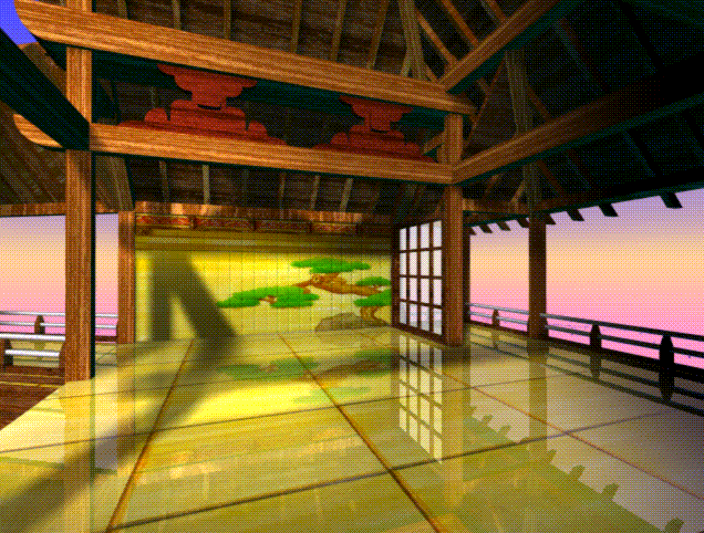
Figure 3.6 Sample ray traced image
Pixel Filter
Determines the method by which anti-aliasing is performed. There are five algorithms to choose from. Box, Tent, Tentc, and Gaussian produce increasingly anti-aliased images. Anti-flicker is a special filter that can be used for broadcast images.
Compute Matte?
Specifies whether a matte is computed for the output image. If you select Yes, the resulting image will be a four-channel (RGBA) image, with the appropriate matte in the alpha channel. If No, the resulting images will be a three-channel (RGB) image.
Dither Image?
Dithers the image to smooth the banding that can sometimes occur in a rendered frame.
Enable Shadows?
Specifies whether shadows should be calculated when rendering the image.
Show Render Time?
Specifies whether the time to render the last frame is displayed in the N·World UNIX shell.
Display Render?
Specifies whether the rendered image is actually displayed in the destination Output Window.
Save Render?
Specifies whether files are saved to the Output Directory specified above.
Fog Color
The default fog color used with the fog render effects.
Shadow Smoothness
Specifies a factor for "smoothing" the generated shadow. Higher values smooth the shadow more, but take more time to render.
Shadow Map Min and Shadow Map Max
These are the default minimum and maximum values for the size of any shadow map that is created; these values can be overwritten by specifying other values for a particular light. See the section "Shadowing," on page 4-20 for more information.
Saving Preferences
After specifying your render defaults, (CLICK-L) on one of the buttons at the bottom of the dialog box:
Shader Attributes (N-Render)
Shading Model
The are five basic shading models which can be used in N-Render:
Each model uses a subset of the render attributes described below to achieve its "look." The shader attributes that can be specified with each shading model are described in Table 3.1:
Ray Trace
Toggles ray tracing on and off. Ray tracing is the more complex of the two basic models for rendering scenes. Using ray tracing, rays from light sources can be "split" upon encountering an object, with some portion of the ray traveling through the object (if it is not completely opaque) and some portion bouncing off the object in another direction, possibly to interact with another object.
Color
Sets the diffuse (surface) color of an object rendered with this material.
Color Opacity
Sets the opacity of the color of an object rendered with this material. Reducing the color opacity typically produces a glassy appearance on the object to which it is applied. (You might, for example, modify the opacity of a bottle or the lens in a pair of glasses.)
A value of 1.0 creates a completely opaque object, while a value of 0.0 produces a completely transparent object.
- Note. When using shading models that support specular highlights, make sure that the highlight opacity and object opacity match. Otherwise, the object can appear more transparent, while the specular remains more visible.
Specular Color
Sets the color of the specular highlight.
Specular Exponent
Determines the size of the specular highlight on an object rendered with this material. The exponent works differently depending on the shading model selected:
Ambient Gel
This color filter (specified with RGB values) affects only ambient lights. The effect is similar to gels on directional lights. (Imagine putting the ambient light inside a colored sphere, so that any object affected by the light was modified.)
An ambient light filter affects only ambient light hitting an object. This can also be used to give a colored tint to a white light just for selected objects. The effects of an ambient light filter are most visible in shadow areas (since they tend to be affected more by ambient light than areas illuminated by directional lights).
Directional Gel
Similar to Ambient Gel above, except that the filter affects only non-ambient light sources (infinite, point, and spot lights).
Like an ambient light filter, this can be used to give a colored tint to a white light just for selected objects.
Fresnel
The Fresnel color is available only with the Cook shading model; it sets the color for the perimeter of the area defined by the specular highlight, creating a two-tone specular highlight.
Visibility
Sets the visibility for an object rendered with this material. For example, if you wanted to make an object gradually disappear, you could write a script in N-Dynamics that animated the visibility for this material from 1 down to 0. Specify the attribute using a value between 0 and 1, with 0 being completely invisible.
Highlight Opacity
The relative opacity of the specular highlight. A value of 1.0 makes the specular highlight completely visible, a value 0.0 makes it invisible.
- Note. This value should match color opacity if you want both the surface opacity and the specular's opacity to have the same value.
Facing Control
Specifies which faces are rendered. For example, you may have cases where you want back faces rendered (e.g., for a wine glass), but other where you don't (e.g., a house).
Smooth Shade?
Selects the interpolation method used to render a scene. Smooth shade creates a smoother transition between neighboring faces, giving the object rendered with this material an overall smoother appearance.
- Note. When using the Phong, Blinn, or Cook shading models, render the scene with Smooth Shade selected.
Light Group
Select the light group used to be used with this material. (CLICK-M) on this field to open the Light Group editor. For details on using the light group editor, see "Lights," on page 4-1.
- Note: To make a light affect one object but not another, you must first assign that light to a light group, then use that light group in the material you use to render the object.
Mapping Attributes (N-Render)
Image mapping is a powerful technique in computer graphics for defining the rendered appearance of a three-dimensional object. In image mapping, a two-dimensional image is used to determine the color, opacity, bumpiness, or reflectance of the surface of a three-dimensional object.
By using mapping, you can substantially increase the visual interest of rendered objects. When you do mapping, you are in essence laminating an image to the surface of an object. Any image in TIFF, TPX, or SGI format can be used as a source image for mapping. For example, you can use frame grabbed, painted, rendered, or algorithmically derived images.
N-Render supports five different types of maps, all of which are discussed later in this chapter:
Sample Maps Directory
A number of sample maps are stored in the following directory:
- /usr/local/ngc/presets/maps
Some of these maps are used to build the preset materials; you can also use these maps to build your own materials.
- Note. This directory is read only, so you won't accidentally erase any maps. Store any maps you create to a different directory.
Visualizing the Mapping Process
To help you visualize the mapping process, imagine wrapping a Christmas present in a square sheet of paper.
First, you have to decide how to line up the pattern of the paper with the object. Perhaps you want to align a particular motif with some dominant feature of the object. You might, for instance, want the image of Santa Claus on the wrapping paper to end up on the top of the package.
You must also decide how to tuck and fold the excess paper so the package looks neatly wrapped and the pattern lines up in such a way that it appears to match across the seams. When you map with N-Render, you can stretch your "wrapping paper" quite a bit, almost as if it were rubber. Of course, if you stretch your "paper," you also stretch the "pattern" in the same way as you might distort an image printed on a balloon when you inflate the balloon. Further, you can stretch one part of your "paper" more than others and get still other effects. Imagine a wrapping-paper image of Santa Claus, for example, acquiring oversized, pointed ears like those of his elfin helpers.
You can map a 2D image with no distortion, but only to the three following geometric primitives:
Mapping to any other surface induces some degree of distortion. This distortion can take the form of unequal scaling (whereby equally sized areas on the map are unequal on the mapped surface) or unequal orientation (whereby angles are not preserved in the mapping process; right angles, for example, become acute or oblique angles). The introduction of distortion is referred to as the general cartographer's problem because it arises in any attempt to project a spherical earth to a flat map.
Because the source image is of finite resolution, an image tends to blur when the mapping process severely distorts it. Blurring can also occur when the texture is mapped to a surface whose projected screen area is greater than the texture map itself.
Blurring can also occur on a texture-mapped object that is severely distorted by perspective. A prime example is a checkerboard placed so that its left and right edges appear to converge at infinity. At some point before the virtual horizon, the board blurs to gray.
Texture Mapping
With texture mapping, you are laminating color onto the surface of an object. With texture mapping alone, for instance, you could apply an image of wood grain or a brick pattern to all the faces of an object, thereby creating the illusion that it was made of wood or brick:
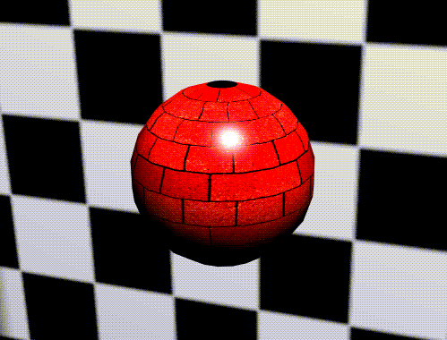
Figure 3.7 Brick texture applied to sphere
Opacity Mapping
With opacity mapping, you are laminating the pattern of opacity. You could use opacity mapping by itself to make parts of the object completely transparent (so the object appeared to have a hole in it) or to give an object some level of transparency (like frosted glass).
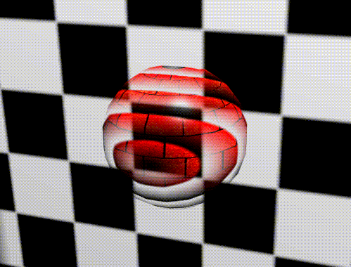
Figure 3.8 Brick texture map and ringed opacity map applied to sphere
Bump Mapping
Bump mapping produces the appearance of an embossed surface, creating the illusion that the object's surface has fine-scale geometric detail, complete with highlights and shadowed edges. As a simple example, imagine that you have created a sphere in N-Geometry, but your ultimate goal is to render a golf ball. Rather than rebuild the object with the fine-scale geometry required to produce the hundreds of dimples on a golf ball's surface, you could create a bump map of dimples and map it onto the surface of the sphere.
The silhouette edge of a bump-opacity-mapped surface is still a polygonal edge; the true geometry is not altered, only the shader's "perception" of it. The illusion of surface texture is frequently strong enough to overcome this limitation. In addition, because bump-opacity mapping mimics fine-scale geometry, the rendered image can have significant amounts of specular aliasing as the simulated "facets" catch sharp highlights. You can modify the "depth" of these facets through the Attributes Editor.
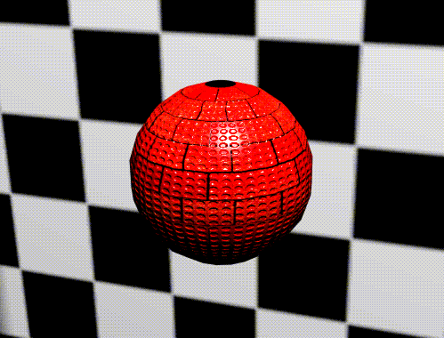
Figure 3.9 Dot pattern bump map applied with texture to create "golf ball" effect
Texture maps and bump maps automatically have opacity maps associated with them (based on the alpha channel of the mapped image-see the section "Use Map Alpha," on page 3-29).
Reflection Mapping
Reflection mapping, used to simulate highly polished surfaces, is especially effective in conveying the impression of a metallic surface such as chrome or gold. This technique establishes (on a pixel-by-pixel basis) what the eye should see reflected in the surface of an object.
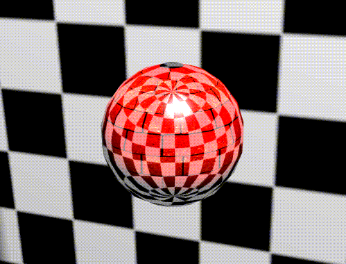
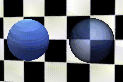
Figure 3.10 Checkerboard pattern applied as reflection map at 50% opacity
Refraction Mapping
Refraction mapping, on the other hand, creates the illusion of what the inside of an object to which the mapper is applied should look like.
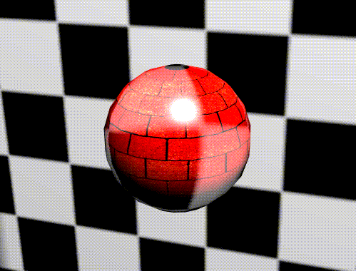
Figure 3.11 Checkerboard pattern applied as refraction map at 50% opacity
Both map types enable you to make the image reflected back to the viewer a "world view" of the object's immediate environment. You would expect the chrome bumper of an automobile parked by a stand of trees, for example, to reflect some portion of the image of the trees.
Reflection and refraction maps do not need mappers, since the surface geometry of the object determines how the map appears on the surface.
N-Render Image Mapping Parameters
N-Render mapping parameters are divided into five major areas. Each of the five types of image map supported by N-Render has its own "slot" in the Material Parameters section-(CLICK-L) on a slot to select it.
Table 3.2 shows which parameters can be specified for each type of map; each of these attributes is described in more detail on the pages that follow.
Map
Specifies the image to be mapped onto the surface of the object.
Opacity
Defines how much of the applied map to be used (expressed as a percentage) versus the diffuse color.
- Note. This attribute should not be confused with an opacity map, which controls opacity of the object. This attribute affects only the transparency of the applied map.
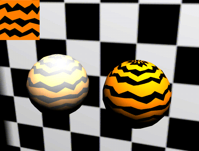
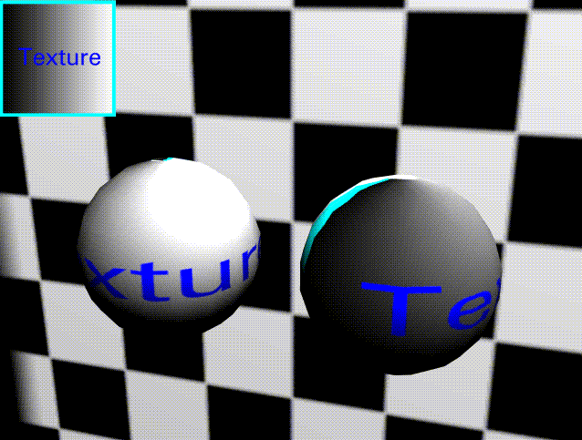
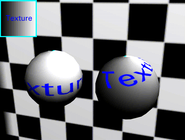
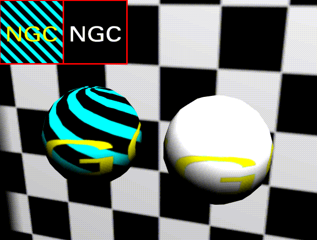
Figure 3.12 Left, sphere with texture map of 50% opacity; right, with 100% opacity (map is shown in upper left corner)
Opacity is expressed as a value between 0 and 1, with values of 0 completely transparent and 1 completely opaque.
Brightness
Modifies the relative brightness of the applied map. The default value is 1.0.
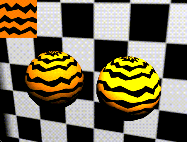
Figure 3.13 Left, sphere with brightness of 1.0; right, with brightness of 2.0
UV Scale
The UV scale for a map determines how an image is repetitively mapped onto an object or face part. You can raise either U or V to a value greater than 1 to apply the map to the same object more than once.
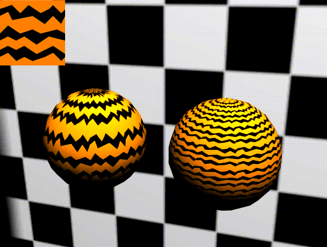
Figure 3.14 Changes in UV scale: left 3,1; right 3,3
UV Offset
Specifies the offset (from the mapper's origin) at which to begin applying the map.

Figure 3.15 Changes in UV offset: first 0,0; second .25,0; third 0,.25, fourth .25,.25
Figure 3.15 shows how different offset values affect mapping of an image onto a surface; in this case, a texture applied through a planar mapper to a lamina:
Figure 3.16 Left, unmodified UV Offset, right, with a negative U value of .3
UV Rotate
Rotates the map by the specified number of degrees before applying it to the object or face part.

Figure 3.17 Changes in UV rotate: left, 0 degrees; middle, -45 degrees; right, 90 degrees
The map is pinned at the 0,0 UV before it is rotated.
Figure 3.18 Left, original; right, rotated 25 degrees
Clip Texture?
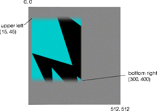
Applies only a portion of the specified map file onto the object or face part. Note that the map is clipped:
Figure 3.19 Clip map applies only a subportion of the image file to the object or face part
This feature can be used, for example, to clip the edges from a map that has been applied through a mapper that is larger than the object.
Shader
Sets the sampling quality of texture mapping. The sampling quality depends on the shader selected. In order of increasing quality, the available shaders are:
(CLICK-L) on shader, then select the sampling method you want to use from the pop-up that appears.
- Note. Using a higher quality shader typically requires longer image rendering time.
Clipping Range
Creates a range (an area between two imaginary planes), and allows the application of maps only when the object is between those two planes (measured in world units, with respect to the camera).
The two values specify the minimum and maximum distance between which maps are applied. Once an object moves out of the specified range, maps are no longer applied to the object.
This feature can be used to make objects that move far away in the scene (where they require less detail) render faster.
Use Map Alpha
Specifies whether the alpha channel for a map should be used when determining which part of the map to apply to the surface of the object. This feature can be used to create a "decal" effect on an object-create a matte under the portion of the map that you want to use, then set this attribute to Yes.
Figure 3.20 The map and alpha channel used on the sphere; left, with map alpha off (ignoring the matte), right, with it on (using only that portion of the matte with a matte)
Boundary
If you set the mapper value smaller than an object, or specify a UV Scale greater than 1, an image is recursively mapped on an object. In either case, you can specify the recurrence pattern to be used when mapping on an object. (In some cases, the map repeats; in others, it mirrors around an axis as indicated by the patterns shown below.)
Consider the application of the following texture map:

Figure 3.21 Sample texture map
The map boundary can strongly affect the appearance of the rendered object. For example, consider the texture map in Figure 3.21 as applied through a planar mapper to the same lamina, using different Map Boundary techniques:

Figure 3.22 Sample of different map boundary parameters; in order, STD, U, V, and UV map boundary
Color Scale
Texture, opacity, reflection, refraction
Modifies the color of the map applied to the object. The color specified works like a filter applied to the map, so that it takes on a tint of the specified color.
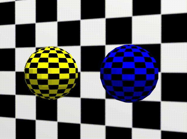
Figure 3.23 Color scale-grid behind spheres with original texture map; spheres using yellow and blue color scales
Background Color
Reflection, refraction
If you are using a partially opaque reflection or refraction map, N-Render needs to know what "color" to use to give the object a correct appearance.
The calculated background color for any reflection or refraction mapping.
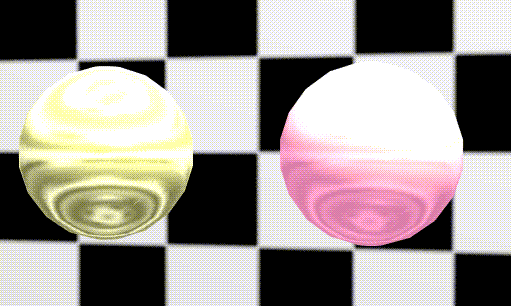
Figure 3.24 Two yellow spheres. Left, with 50% opacity reflection map, and white background color; right, with 10% opacity reflection map, and magenta background color.
Depth
Bump
Controls the steepness of the bump texture walls. Bump depth is expressed using both U and V values; higher values cause the texture to appear bumpier. Both U and V coordinates can be specified, so you can make either the vertical or horizontal "bumps" more prominent. A higher U value accentuates the horizontal bumps; a higher V value accentuates the vertical bumps.
U and V values may be between the values of -10 and 10.
Figure 3.25 Apparent effect of positive and negative bump depth values
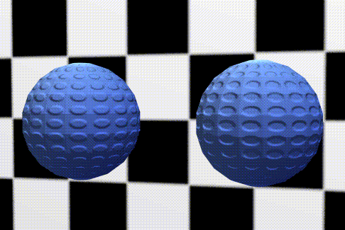
Figure 3.26 Left, bump map using positive values; right, bump map using negative values
Increasing the value in either direction makes the bumps more prominent, as shown in Figure 3.27.
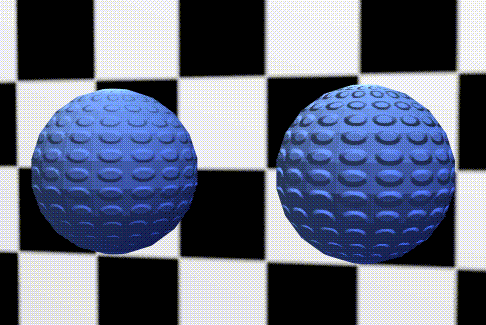
Figure 3.27 Left, bump map value of 1.0; right, bump map value of 3.0
Index
Refraction
Used only with refraction maps, this value modifies how the refraction map is applied to the object. A higher value causes more of the "refracted" scene to be applied to the object. To use this, you'd probably want to use a map of the rendered scene itself as your map.
The example in Figure 3.29 was created using the following map:
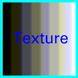
Figure 3.28 Sample map
The map is inverted and applied to the object as shown in Figure 3.29:
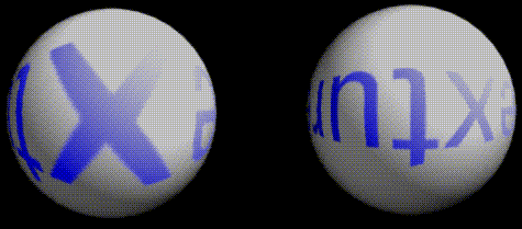
Figure 3.29 Modifying the refraction index; left, 1.33; right 2.0
Effects Attributes (N-Render)
These special effects attributes are only available with the Render domain.
Oblique Effects?
When rendering a semi-transparent object, such as a glass sphere, its edges typically become more opaque and light more diffuse at the outside of the object, since you are actually looking through a greater amount of opaque material at the outside of the object (the viewpoint along line A in the figure below). When viewing the object directly, you are looking through a thinner wall (the viewpoint along line B in the figure below).
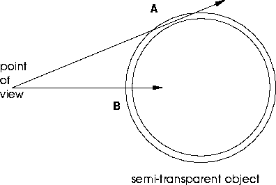
Figure 3.30 Oblique effects
(CLICK-L) on Yes to display the oblique effects attributes.
- Note. If you are using oblique effects when creating a material, you may need to modify shadow lights used in rendering a scene that includes semi-opaque objects. Changing an object's transparency does not affect the intensity of the shadow cast by that object; you must modify the shadow light's brightness for the shadow to look realistic.
Diffuse
Specifies how light is diffused along the edges of an object when using oblique effects. Diffusion is specified using center, outside, and exponent values:
Opacity
Specifies the opacity of an object when using oblique effects. Opacity is specified using center, outside, and exponent values:
Figure 3.31 Left, sphere with no oblique effects; right, with opacity oblique effects. Note the edges of the sphere on the right are more opaque than the center of the sphere.
Specular
Specifies the characteristics of the specular highlight when using oblique effects. (For a realistic effect, these should be the same as the values defined for the opacity of the object.)
Higher values create a more opaque highlight.
Reflect
Determines how reflection maps are applied to an object when using oblique effects.
Refract
Determines how refraction maps are applied to an object when using oblique effects:
Use Fog?
The process used for making objects disappear into a "fog" as they move away from the camera.
Select Yes to use fog, then modify the parameters below to define its effects.
Fog Limit
These two values define where the fog effect begins, and where it increases to 100% opacity. The distances are expressed in units in which the scene is rendered, measured from the camera's point of view.
At the minimum distance, the fog has an opacity of zero; at the maximum distance and beyond, it has an opacity of 100%. Objects moved toward the maximum distance appear to disappear into a fog of the specified color.
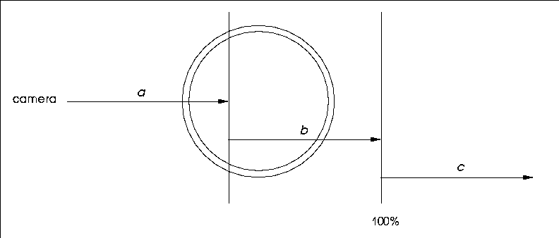
Figure 3.32 Fog limits. a is the distance from the camera at which the fog starts; b the range over which the fog effect increases from 0% to 100%; objects in "c" are enveloped in the fog at 100%
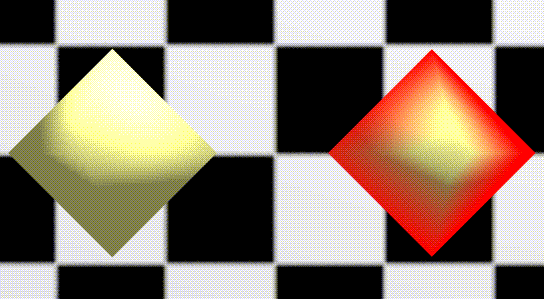
Figure 3.33 Left, octahedron with no fog effect; right, with partially past minimum fog limit
Use Default Color?
If set to Yes, the default fog color specified using the Render Defaults menu is used. If set to No, a color edit box appears; (CLICK-L) on the color box to edit the color of the fog.
[N-World Contents] [Book Contents] [Prev] [Next] [Index]
 Another fine product from Nichimen documentation!
Copyright © 1996, Nichimen Graphics Corporation. All rights
reserved.







 Another fine product from Nichimen documentation!