PARTICLE SYSTEM
|
Introduction
|
|
|
 Particle is a pixel-based particle generation system
that lets you create three-dimensional animation that simulates natural phenomena
containing many particles. For example, Particle makes it easy to animate sparks rising
from a campfire, fireworks, or the tail of a comet trailing off into space.
Particle is a pixel-based particle generation system
that lets you create three-dimensional animation that simulates natural phenomena
containing many particles. For example, Particle makes it easy to animate sparks rising
from a campfire, fireworks, or the tail of a comet trailing off into space.
Particle lets you create a system of particles, emitted from a given
source. You can then link the particle system to a model imported from SOFTIMAGE 3D, and
render a scene. For example, you can create a stream of particles that looks like spraying
water, and link the source of the particle stream to a model of a garden hose that you
built in SOFTIMAGE 3D. When you composite the particle scene over the 3D
scene, it will look like the hose is spraying water.
How it works
Partice does not animate geometrical objects the way SOFTIMAGE 3D does. From each
source, or emitter, a uniform series of small shapes (particles) are
created, which represent points in 3D space. The rendering process applies a spot of color
( or 2d image) at the location of the particle, much like a brush stroke. This process
permits large numbers of particles in a scene without making the scene take up too much of
your computer's resources
PARTICLE SYSTEM
|
Physics of
particle animation
|
|
|
Particle offers a realistic simulation of particle dynamics by applying forces and
recreating events that happen to natural particles. You determine how particles behave by
defining parameters, for the following categories:
- Natural Forces
- Disintegration
- Collisions
Natural Forces
You can apply electric and magnetic forces, gravity
and wind. These forces can act locally or globally upon particles in any
direction in 3D space.
Disintegration
A particle's lifespan begins the moment it is generated form a source, and ends when
the particle decays or dies. Particles in a system may change color
during their lifetimes. When a particle decays, it may emit one or more new particles from
its current location. An example could be a fire particle that emits
smoke particles at the end of its lifetime.
Collisions
 There are three types of collisions
which may involve one or many types of particles:
There are three types of collisions
which may involve one or many types of particles:
Internal collisions occur when particles emitted from a source collide
with each other, or when identical particles from different sources collide. (These
collisions are controlled via the sigma value in the Particle
Module.)
Simple collisions occur between two different types of particles
coming from different sources. ( These collisions are controlled through the Collision
Module).
Complex collisions occur when new particles are created as a result of a
collision between two or more different types of particles from different sources. The
number of new particles created is independent of the number of particles that are
colliding. (These collisions are controlled through the Event Module).
How to use Particle
This is an overview of the procedure you use to create particle animation:
 1. Define the source.
The first step involves defining the source or origin of the particle emission. You can
position the source within a scene imported from SOFTIMAGE 3D, or choose an element from
the scene hierarchy to use as the source. The source can also be defined directly in
Particle, without using a scene from SOFTIMAGE 3D.
2. Define the particle type.
This step involves setting the characteristics of the individual particles. These
characteristics include the lifetime of the particles in the stream, their rendering
attributes, their physical attributes, and their internal collision rate.
3. Link the particle type to the source.
This is the step where you assign a particle type to a source, and choose the method in
which the particles will be emitted.
4. Create obstacles for the particle stream.
 If desired, obstacles can be set to
interact with the particle stream. The particles can be made to bounce
off or stick to the obstacle. They can also be made to disappear or to decay
once they strike the obstacle. A model from a scene imported from SOFTIMAGE 3D can be used
as an obstacle. Obstacles can also be created directly in Particle, without using a model
from SOFTIMAGE 3D.
If desired, obstacles can be set to
interact with the particle stream. The particles can be made to bounce
off or stick to the obstacle. They can also be made to disappear or to decay
once they strike the obstacle. A model from a scene imported from SOFTIMAGE 3D can be used
as an obstacle. Obstacles can also be created directly in Particle, without using a model
from SOFTIMAGE 3D.
5. Define collisions and events.
If desired, simple and complex collisions can be created in scenes containing multiple
particle streams. Simple collisions happen between two different types of particles coming
from different sources. Complex collisions or events occur when other particles are
created as two or more different types of particles collide. The number of new particles
created is independent of the number of particles that are colliding.
6. Render and play back the Particle scene.
If you are incorporating the particle system within a 3D scene, you must follow this
procedure:
Render the 3D scene within SOFTIMAGE 3D, using the SOFTIMAGE renderer with the Render
z Channel option selected in the Render Setup Options dialogue
box.
Load the 3D rendered images into the Particle renderer as background images.
Load the rendered z channel into the Particle renderer as Z Channel.
Render the particle animation. The particle animation is composited
using the depth information from the z channel of the 3D rendered
pictures to create seamless three-dimensional animation with a particle effect.
PARTICLE SYSTEM
|
3D Viewing
area
|
|
|
 The largest region in the
Particle interface is the 3D viewing area. Your 3D particle animation is
displayed here.
The largest region in the
Particle interface is the 3D viewing area. Your 3D particle animation is
displayed here.
The 3D viewing area is where you view and manipulate objects. The 3D viewing area
contains one Perspective projection view and three parallel
projection window views (Right, Front, and Top).
It also contains a camera (Cam) view, which is used only when camera
information is loaded with an external 3D scene. By default, the Perspective view is
displayed when you start the software.
You can change the default window view by clicking on one of the five options, which
are located at the top of the 3D viewing area.
Manipulating Elements in the 3D Viewing Area
 In the 3D viewing area you may scale,
rotate and reposition the following elements: sources, obstacles, and local electrostatic
& magnetic fields.
In the 3D viewing area you may scale,
rotate and reposition the following elements: sources, obstacles, and local electrostatic
& magnetic fields.
Each element that can be manipulated has 3 yellow circles around it, one for each axis,
defining a sphere in 3D space. Surrounding this sphere is a set of colored arrow heads
pointing in the direction of the global coordinate axes, located in the
lower left corner of the viewing area.
The element's center or origin is defined by three colored arrows, which point in the
direction of the element's local X,Y and Z axes.
Rotating: By holding the left mouse button down and dragging from one
of the circles, you will rotate the element along the corresponding axis. Note the local
origin rotates with the object, but the surrounding arrow heads maintain their original
positions, aligned to the global coordinates.
Repositioning: The outer colored arrow heads are used to translate
along the 3 coordinate axes. Dragging the mouse from the green arrow head moves the
element along the y-axis; red is used for the x-axis, and blue is used for the z-axis. You
may also click directly on the center point to freely drag the element vertically and
horizontally.
Scaling: Use the three colored arrows emanating from the center point
to size the object along any one of its own local axes.
Direction: For sources, the white arrow (pointing up
from the source in this illustration) can be manipulated to control the direction
in which particles are emitted.
 Each module has a unique set of parameters used to
define your 3D particle animation.
Each module has a unique set of parameters used to
define your 3D particle animation.
There are six modules:
- Particle
- Source
- Obstacle
- Collision
- Event
- File
These modules let you choose between groups of parameters for defining the particle
animation. When you select a module, the corresponding parameter controls appear in the parameters
area on the right side of the display.
Modifications made to a particular module's parameters effect only the element
corresponding to that module. For example, if you change the value of a parameter in the
Source module, that change is applied to the source emitter.
PARTICLE SYSTEM
|
Parameters
area
|
|
|
 This is where Module-specific
properties are selected for editing.
This is where Module-specific
properties are selected for editing.
Each module has its own unique set of parameter control buttons. Parameter
control buttons are important tools for interacting with the software, they
contain the various rules that govern the behaviour of the different elements contained in
your scene. Some control buttons open dialogue boxes, while others open lists of elements
that you have created. The control buttons for each module are described in the
corresponding MODULES section .
Command Buttons
The New, Copy, and Delete command buttons are found in the parameters area. These
functions can be performed on particles, sources, obstacles, collisions, or events.
The File module contains a unique set of command buttons, (Load, Merge, Save, Sequence,
and Reset) that are available only when File is selected. They are used to launch and
control the preview of the Particle effects.
PARTICLE SYSTEM
|
Parameters
editing area
|
|
|
When you select certain parameters in the parameters area, their
corresponding values appear in text boxes in the parameters editing area
below.
 Units appear beside the text boxes. For
Size, you can change Units (un.) to Pixels (pix.) by clicking on the un. button in the
Parameter Editing area.
Units appear beside the text boxes. For
Size, you can change Units (un.) to Pixels (pix.) by clicking on the un. button in the
Parameter Editing area.
When Units is selected, the particle dimensions change depending on their position in
space according to the camera.
When Pixels is selected, the particles always have the same pixel size regardless of
their position in 3D space.
PARTICLE SYSTEM
|
Playback
area
|
|
|
 This is where the controls
are for displaying your animation. It is located in the upper-right corner of the software
display.
This is where the controls
are for displaying your animation. It is located in the upper-right corner of the software
display.
The playback controls allow you to visualize animation in various ways using various
techniques.
Using the Playback Controls
Starting frame text box: Sets the starting frame number.
End frame text box: Sets the end frame number
Forward arrow: Plays back the scene from starting to ending frame.
Stop button: Interrupts the playback. Click the Forward arrow button
to restart the playback.
Option to loop the playback. Click the loop button to activate it and
then click the forward arrow. By middle-clicking the playback arrows, you can play the
animation from the current frame and then loop it from the start frame to the end frame.
Frame advance arrow: Option for frame-by-frame advance. Click frame
advance arrow to move from the current frame to the next frame in the sequence.
Backward Frame arrow: Moves back from the current frame to preceding
frames, displaying each frame one at a time. Click the backward frame arrow to move from
the current frame to the previous frame in the sequence.
Start frame arrow: Returns to the starting frame of your animation.
End frame arrow: Advances to the last frame of your animation.
Particles are emitted only during a playback (that is, when the forward arrow is
clicked). In other words, you cannot view the particles frame-by-frame.
PARTICLE SYSTEM
|
Status bar
|
|
|
The status bar is located at the bottom of the software display. It
contains the timeline and the message line.
Timeline
Click anywhere along the timeline to move the pointer to that position, or drag the
pointer with the mouse.
Dragging the pointer while pressing the left mouse button updates the sequence frame by
frame.
The current frame number is displayed on the right side of the timeline. Click in the
box to insert a number; middle or right-click to replace the current frame number.
Message Line
If you click on the word `Message' in the status bar with any mouse button, a window
will open displaying every message recorded during the current session (that is, from the
time you started Particle).
PARTICLE SYSTEM
|
Creating
keyframe animation
|
|
|
Whenever a parameter text box has a key button (see picture below)
next to it, the value can be keyframed. When entering keyframes for a parameter, remember
to follow the correct procedure:
- Use the timeline to select the frame to be keyed.
- Adjust the value of the parameter, with the virtual slider or by typing data into the
text box.
- Click the key button with the left mouse button and select Set Key.
 If you click the key button and chose Edit
Curve, the Graph Editor will pop up. You can then edit the
animation curve that corresponds with the keyframes.
If you click the key button and chose Edit
Curve, the Graph Editor will pop up. You can then edit the
animation curve that corresponds with the keyframes.
Previous Key and Next Key will allow you to navigate
between keyframes.

PARTICLE SYSTEM
|
Preview
sampling area
|
|
|
 The preview
sampling rate slider is located immediately below the left corner of the 3D
viewing area.
The preview
sampling rate slider is located immediately below the left corner of the 3D
viewing area.
This slider allows you to interactively reduce the number of particles that are
displayed when previewing your animation. If your animation contains a complex scene,
reducing the number of particles that are displayed, helps speed up playback.
PARTICLE SYSTEM
|
Natural
forces application area
|
|
|
This area is located at the bottom of the 3D viewing area. It includes, Local
controls that can be applied to a selected area in 3D space, and Global
controls that are applied to the entire scene.
There are four global natural force controls and two local natural force controls -
Magnetic, and Electric can be applied locally and globally, whereas Gravity, and Wind can
only be applied globally. When one of the natural force controls is selected a dialogue
box appears, and a corresponding icon appears in the 3D viewing area.
Electric simulates an electric field by attracting or repelling the
particles.


Magnetic simulates a magnetic field by creating a whirlpool effect on
the particles.


Gravity simulates a gravitational field acting on the particles.


Wind simulates the effects of wind on the particles.


In addition to defining the strength and direction of each field, you may define how
strongly each particle is affected by that force.
PARTICLE SYSTEM
|
Entering
and editing data
|
|
|
Besides typing a value directly into a parameters text box, or in a dialogue box, you
can also modify a value using Particle's virtual slider capability.
Virtual Slider Operation
Click on the name of the parameter you want to edit; the text will turn blue indicating
that it is selected. The associated value box(es) appears at the bottom of the parameters
editing area.
Press any mouse button; the text will turn red indicating that is possible to edit the
value in the text box.
With the mouse still pressed, slide the mouse to the right or to the left. Moving the
mouse to the right will increase the value in the text box, and moving it to the left will
decrease the value in the text box.
Each mouse button will change the value in the text box at a different speed. The left
button is the slowest, the middle button is faster, and the right mouse button is the
fastest.
PARTICLE SYSTEM
|
Supra key
functions
|
|
|
 In Particle, just as in SOFTIMAGE 3D,
many operations can be performed by using keyboard shortcuts, called Supra keys.
In Particle, just as in SOFTIMAGE 3D,
many operations can be performed by using keyboard shortcuts, called Supra keys.
Pressing Shift + h opens a Help window (figure shown at left) that
displays a scroll list of mouse and keyboard shortcut commands (supra key functions).
You can leave the Help window open for the duration of your Particle session until you
are familiar with the various shortcut keys.
To reposition this window, or any other pop-up window, place your cursor in the window,
press Alt + right mouse button and slide the cursor to the Move option which appears (Alt
+ F7 is the shortcut). Release Alt and the mouse button, and drag the mouse until the
window frame is in the desired location. Then click once with any mouse button.
PARTICLE SYSTEM
|
Source
Module
|
|
|
The Source
module lets you create and define sources of particles. Each source is classified
according to its name and the type of particles it emits. Each source can emit only one
particle type. The nature of the source is determined by its parameters. When you select
the Source module (or press the F2 key), the source controls appear in the parameters area
as shown on the left.
The first time you enter the Source module, the parameter control buttons are dimmed,
indicating that they can not be accessed. When you click on New, to
create a source, these parameters become activated.
In addition to creating new sources, you can copy, delete
and edit the names of sources.
Particle type
To select a type of particle for the source to emit, click on the arrow to the right of
the Particle text box. and you will see a pop-up list of all particles currently defined.
 If you create a new source and no
particles are yet defined, a default particle, PARTICLE_1, is assigned to the source.
If you create a new source and no
particles are yet defined, a default particle, PARTICLE_1, is assigned to the source.
(The picture shown is a detail from the Source Module card.)
Visibility
Toggle Visibility off when you have a complex session containing many different
sources. The particles from these sources will not be displayed on the screen, allowing
you to concentrate on one source at a time.
Source parameters
The following parameters allow you to control the behavior of particles emitted from
the selected source:
- Geom
- Link
- Generation
- Emission
- Regular Stream
- Position, Scaling, Rotation
- Direction
- Spread
- Rate
- Inherit Velocity
- Speed
- Speed Limit
Geometry
 Lets you select the basic
geometry of the source area. You can choose between procedural objects (such as a POINT,
LINE, SQUARE, DISK, CUBE, or SPHERE) to define your source geometry, or you can select a
3D OBJECT in a scene loaded from SOFTIMAGE 3D.
Lets you select the basic
geometry of the source area. You can choose between procedural objects (such as a POINT,
LINE, SQUARE, DISK, CUBE, or SPHERE) to define your source geometry, or you can select a
3D OBJECT in a scene loaded from SOFTIMAGE 3D.
Link
The Link button to the right of the Geom text box lets you link a procedural emitter to
an object in a loaded scene.
PARTICLE SYSTEM
|
Source
parameters
|
|
|
Generation
 Specifies where the
particles will be generated, according to the geometry of the source. When you click on
Generation the following options appear:
Specifies where the
particles will be generated, according to the geometry of the source. When you click on
Generation the following options appear:
POINT
- Particles are generated from the center of the source.
LINEAR
- Particles are generated along the x-axis of the source.
SURFACE
- Particles are generated across the surface of the source.
VOLUME
- Particles are generated inside the source
Emission
 Controls the direction
of particle emissions according to conditions that you assign. When you click on Emissions
the following options appear:
Controls the direction
of particle emissions according to conditions that you assign. When you click on Emissions
the following options appear:
RELATIVE
- Particle emission is determined by the emitter reference
(white arrow located on the source object).
ABSOLUTE
- Particles are emitted relative to the world reference
(white arrow located at the bottom right corner of the 3D viewing area).
NORMAL
- Particles are emitted according to the geometric normal.
PATH
- Particles are emitted along a named path.
Emission by Path is a major feature of the Particle program. Particles can be assigned
to a given path, and the software will compute the forces it needs to apply to the
particles so they follow the path. This process is called inverse dynamics.
Whatever path you choose, the computation of the particle stream is performed with the
path translated to the position of the source.
Regular Stream
 Generates a more uniform flow of
particles by emitting them in an evenly spaced manner in time.
Generates a more uniform flow of
particles by emitting them in an evenly spaced manner in time.
 Position, Scaling, Rotation
Used to reposition, resize, or reorient the source in the 3D world, or in relation to
its parent object (if a parent object exists). There are two ways to manipulate source
objects:
- enter X,Y and Z values directly in the parameter editing area text boxes, or
interactively manipulate the source object using the mouse in the 3D viewing area.
(Take this link back to review the 3D viewing area.)
Direction
Determines the inclination
and the azimuth of the vector along which the particles are emitted.
Inclination, measured in degrees, is the angle between the emission
vector and the Y axis. Azimuth is the angle of rotation of the emission
vector about the Y axis.
 When emission
is set to RELATIVE the direction of particle emission is indicated by the
emitter reference, a white arrow extending from the center of the source object. When emission
is set to ABSOLUTE the direction is indicated by the world reference, a
white arrow located in the lower right corner of the 3D viewing area.
When emission
is set to RELATIVE the direction of particle emission is indicated by the
emitter reference, a white arrow extending from the center of the source object. When emission
is set to ABSOLUTE the direction is indicated by the world reference, a
white arrow located in the lower right corner of the 3D viewing area.
You may alter the direction of particle emission either by using the text boxes in the parameters
editing area, or by directly manipulating the white arrow in 3D space.
Spread
Controls the aperture through which the particles are emitted from the source,
according to the direction of emission. The spread is measured in degrees.
Rate
Determines the number of particles emitted per second.
Inherit Velocity
Controls the velocity of the particle emissions from a moving source, or from an
animated 3D object that you are using as a source, or from moving vertices of shape
animation objects. You apply a percentage value which is relative to the velocity of the
source, or to the velocity of the moving vertices. That is to say, the emitted particles
will inherit the specified velocity from the moving source, or vertices.
If you specify a value greater than 1, the particles are emitted at a greater velocity
than the emitter's velocity, therefore causing them to speed ahead of the emitter. If the
value is less than 1, the particles will not inherit the velocity of the emitter,
therefore causing them to trail behind the emitter.
Speed
Determines the initial speed of the particles in units per second.
Path Strength
A percentage value that allows you to control how precisely the particles are
translated along the profile of a spline that has been imported from SOFTIMAGE 3D.
Speed Limit
Allows you to set the range, and maximum/minimum speed that the source emits the
particles. This control is useful when the particles speed increases due to high local or
global field values such as magnetic or electric. Setting a maximum speed, with Speed
Limit, eliminates this problem.
PARTICLE SYSTEM
|
Parameters
|
|
|
The Particle parameters let you define and characterize the different types of
particles that will be emitted by the particle sources in your animation. You can define
as many particle types as you want, but only one particle type will be emitted from each
source.
Particle parameters
The following physical parameters can be defined for particles:
 Friction -
controls the effect of drag on the particle, to simulate a particle traveling through a
medium.
Friction -
controls the effect of drag on the particle, to simulate a particle traveling through a
medium.
Electric
- the amount of influence an electric field in the scene will
have on the particle
Magnetic
- the amount of influence a magnetic field in the scene will
have on the particle.
Mass
- controls the behaviour of particles in collisions. A heavier
particle's momentum will displace the lighter particle.
Life Time
- determines the amount of time, in seconds, the particle
will exist. At the end of this time, the particle decays or dies.
Trail Life
- determines the amount of time, in seconds, that a trail
effect will remain behind the particle as it travels in space.
Noise
- adds a jitter effect to a particle. This will affect the
position(P), velocity (V), and acceleration (A) of the emitted particle.
Sigma -
determines the internal collision rate between particles of
the same type.
Decay
- This feature permits the particle to generate other particles
upon reaching the end of its lifetime. The Decay Parameters dialogue box
allows you to define how the newly generated particles will behave.
PARTICLE SYSTEM
|
Rendering
attributes
|
|
|
Multiplication
 Toggle on
Multiplication to define the Number of instances you wish to reference to the original
particle, and the physical relationship � Size Factor and Radius � the instances have to
the original particle.
Toggle on
Multiplication to define the Number of instances you wish to reference to the original
particle, and the physical relationship � Size Factor and Radius � the instances have to
the original particle.
Number
Lets you specify the number of instances generated from the original particle.
Size Factor
Controls the size of the instances, which are defined as a percentage relative to the
original particle (100% is the actual size of the original particle). The instances have a
1-to-1 size relationship with the original particle. If you edit the size of the original
particle, the instances are altered by the same percentage.
Radius
Determines the distance, in units, that the instances are positioned relative to the
original particle.
Glow
 When you toggle on the Glow
parameter, the RGBA value of each particle is added. At the source, the color contains the
full saturation of its RGB value since the maximum number of particles exist at this
position. When the particle reaches the end of the Life Time value, there are fewer
particles to add, so the color is less saturated, resulting in the glow effect.
When you toggle on the Glow
parameter, the RGBA value of each particle is added. At the source, the color contains the
full saturation of its RGB value since the maximum number of particles exist at this
position. When the particle reaches the end of the Life Time value, there are fewer
particles to add, so the color is less saturated, resulting in the glow effect.
Color Dialogue Box
Colors can be expressed according to RGBA or HLSA values. Additionally, the Sprite
option, allows you to map a picture file onto each particle generated by a source. When
you toggle on the Sprite option, a database browser appears letting you load a 2D image or
a sequence of images. The image is then mapped to each particle. There are three ways in
which you can assign color to a particle:
- The color of the particle can be constant for the duration of its
lifetime.
- The color of the particle can be keyframed.
- Colored particles and their trails can also be animated according to different time
references in the particle's lifetime causing the colour of the particle to change over
time. This is called animating the color shift of the particle.
When you click on the Color... button in the Particle module, the
following dialogue box appears.

Keyframing the color of the particle
- Move the timeline to the desired frame.
- In the Color dialogue box, adjust the color for the current frame, then click the key
button. This will affect the color of the particles emitted from the current keyframe
until the next.
- To animate the color of the particle over its lifetime, select the Color Shift
option.

When you are in Color Shift mode, the color bar represents the
lifetime of the particle. To edit the color bar, follow these steps:
- Click on a part of the black strip that appears under the color bar with the left mouse
button. A red arrow appears which represents a color shift key.
- Use the color sliders under the Color Shift check box to shift the color components up
or down for the color shift key.
- You can continue to add color shift keys as desired. The selected key appears as a red
arrow, and deselected keys appear green.
To add another key, click on the black strip with the left mouse
button.
To select a key, middle-click on the corresponding green arrow.
To move a key, click and hold the middle mouse button down over the
corresponding green arrow and drag the mouse. When the key is in the desired location,
release the middle mouse button.
To delete a key, right-click on the corresponding arrow.
Opacity
Opacity can be expressed according to the Alpha
channel or RGB int. (intensity). At the bottom of the RGBA
editing area you can choose one of the two radio buttons, depending on the effect you wish
to create.
Alpha
uses the alpha channel of the color to create transparency in
the particle.
RGB Int.
uses the RGB color intensity to create transparency in the
particle. It produces a dull effect on the particle.
 Color Editor
The Color Editor displays the selected color and shape that you choose for the
particles. When you modify a color value or select a shape, it is displayed in the Color
Editor immediately.
Shape lets you select a shape to be used as an alpha channel
for the particles in your system. When you click the Shape button, a list of predefined
shapes opens.
Various parameters can be edited depending on the shape you select. You can choose from
among 14 different shapes, or you can select Image and load a 2D image from the database
browser that appears. These shapes include:
 LINEAR - a
smooth illuminated effect, with the centre more brilliant than the edges. It is the
default setting and cannot be edited.
LINEAR - a
smooth illuminated effect, with the centre more brilliant than the edges. It is the
default setting and cannot be edited.
CONSTANT - a solid brilliant effect with no shading.
SMOOTH1 - a tiny, bright centre with a fall off dulling effect towards
the outer perimeter.
SMOOTH2 - an overall hazy effect with gradual dulling towards the
outer perimeter.
SMOOTH3 - an overall flat, dull, matt effect.
GAUSS - a bright centre with an evenly dull, illuminated effect that
ends with crisp, definite edges.
STEP - a bright centre with evenly illuminated edges.
SINE - creates a particle with a editable number of rings that are
equally spaced from one another.
STAR - a bright centre with four illuminated spokes, decreasing in
intensity toward the outer edges.
BEAM - a long beam shape with a bright center surrounded by a glow
effect. You can edit the width of the beam.
SYMMETRY - a cube shape with an overall hazy effect. Two slightly
brighter lines extend diagonally across the surface.
NOISE - can be used to create an infinite variety of patterned
effects. Based on one basic pattern, you can modify the spacing, and the level of detail.
The higher the value that you define, the more compressed the pattern becomes.
TURBULENCE - a 3D (procedural) texture applied to a cylinder at a
given `Z'. When you select TURBULENCE, you can set and keyframe the `Z' channel, Low
Frequency, High Frequency and the Scale value. A marble-like pattern is produced.
FRACTAL - a 3D texture applied to a cylinder at a given `Z'. When you
select FRACTAL, you can set and keyframe: Scale (controls the texture), Granular (refines
the grain), and Weight (controls the luminosity).
IMAGE - opens a browser that displays the picture chapter of the
active database. From here you can select an image that is in SOFTIMAGE file format, or
navigate to the location where your images are stored.
PARTICLE SYSTEM
|
Obstacle
Module
|
|
|
 Any number of obstacles can
be created in a scene. Obstacles can be models imported from SOFTIMAGE 3D, or procedural
objects from the Particle system linked to hierarchies in SOFTIMAGE 3D (A SOFTIMAGE 3D
model has to exist in the associated scene).
Any number of obstacles can
be created in a scene. Obstacles can be models imported from SOFTIMAGE 3D, or procedural
objects from the Particle system linked to hierarchies in SOFTIMAGE 3D (A SOFTIMAGE 3D
model has to exist in the associated scene).
Obstacle Parameters
When you select the Obstacle module (or press F3), the obstacle controls appear in the
parameters area as shown on the left. These controls include:
- Absorb
- Geom
- Link
- Type
- Active
- Position, Scaling, Rotation
- Resilience
- Friction
- Emit
Absorb
The Absorb scroll list allows you to specify different particle types which will
interact with an obstacle. You can add as many particle types to the Absorb list as you
have defined in your session.
The physical properties, below the Absorb list, control only the obstacle,
and affect all particles in the Absorb list .
 Geometry
Selects the basic geometry of the source area. You can choose between procedural
objects (such as a point, line, square, disc, cube, or sphere) to define your source
geometry, or you can select an object in a scene loaded from SOFTIMAGE 3D.
Link
The Link button to the right of the Geom text box lets you link a procedural obstacle
to an animated or static object in a loaded scene.
Type
Allows you to choose the physical property of the obstacle, and how it will interact
with the particle when it is struck. You can choose between five types of obstacles:
 Bounce - Causes
the particles to bounce off the obstacle when they strike it. The particles' speed after
striking the obstacle will be modified according to the dampening factors of the obstacle
(the normal and tangent component of the incoming speed vector are multiplied by the
respective dampening factors).
Bounce - Causes
the particles to bounce off the obstacle when they strike it. The particles' speed after
striking the obstacle will be modified according to the dampening factors of the obstacle
(the normal and tangent component of the incoming speed vector are multiplied by the
respective dampening factors).
Stick -
Causes the particles to stick to the surface of the obstacle
until the particles die or decay.
Disappear -
Causes the particles to disappear when they strike the
obstacle.
Decay
- Makes the particles decay at the point of collision with the
obstacle.
Emit
- Allows you to define new particles which will be emitted when
the absorbed particles strike the obstacle.
Active
When Active is toggled on, the obstacle is visible to the particle types that you added
to the Absorb list. If Active is not activated, the obstacle is transparent to all the
particle types.
Position, Scaling, Rotation
These three options are used to reposition, resize, or reorient the obstacle in the 3D
world, or in relation to its parent object (if a parent object exists).
 Resilience
This feature works only with Bounce or Emit type
obstacles. Resilience controls how particles will bounce off the obstacle when they strike
it. The particles' speed after striking the obstacle will be modified according to the
resilience of the obstacle.
By default, Resilience is set to 100, which means that 100% of the energy of the
particle striking the obstacle will be transmitted back into the rebounding particle, so
the particle will not lose speed after it strikes the obstacle.
 Friction
This feature works only with Bounce or Emit type
obstacles. It controls whether particles will stick to the surface of the obstacle when
they strike it. By default, the friction is set to 100. A lower friction level will cause
the particle to rebound along the vertical axis of the obstacle. A higher friction level
will cause the particle to rebound almost parallel to the obstacle.
Emit
 When you select the EMIT option
from the Type list, its scroll box appears allowing you to specify any number of different
particle types that will be generated from the collisions of the particles with a specific
obstacle.
When you select the EMIT option
from the Type list, its scroll box appears allowing you to specify any number of different
particle types that will be generated from the collisions of the particles with a specific
obstacle.
The parameter controls below the Emit scroll box are used to define physical properties
-- Direction, Spread, Inherit Velocity , and Speed,
--for the particle type that is highlighted in the Emit scroll box.
PARTICLE SYSTEM
|
Collision
Module
|
|
|
Creating Simple Collisions
The Collisions module simulates simple collisions. When two particles
with different masses collide, the "heavier" particle's momentum
will displace the lighter particle.
When you select the Collisions module (or press F4), the collision controls appear in
the parameters area as shown below. These controls include:
 The Collision text
box - contains the name of the collision.
The Collision text
box - contains the name of the collision.
The Parameters section - contains two text boxes labelled #1 and #2,
in which you specify the names of the particle streams that you want to collide.
The Probability text box- determines the probability of a collision
between the particles in the two streams. Within each elementary volume, if the density
of the particles is greater than zero, a collision may occur according to the density of
the smallest particle, the rate of particle emission, and the value
specified in this box.
PARTICLE SYSTEM
|
Event
Module
|
|
|
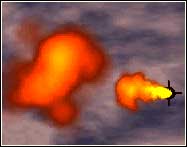
Creating Complex Collisions
Example of a yellow Particle event created with
the collision between the red and black particles.
The Event module is where you define complex collisions.
Here you can specify any number of different particle types emitted from separate sources
and collide them, generating any number of new particles as you wish. The number of new
particles created is also independent from the number of particles that are colliding.
 When you select the Event
module (or press F5), the event controls appear in the parameters area as shown on the
left.
When you select the Event
module (or press F5), the event controls appear in the parameters area as shown on the
left.
The Event text box is where you specify the name of
the event.
The Event Probability button determines the probability of a collision
between the particles selected for the event. The higher the rate, the more likely that
particles will collide with each other.
The Event Parameters section contains two scroll boxes called Absorb
and Emit. The Absorb scroll box contains the names of the
particle types that will be colliding. The Emit scroll box contains the name(s) of the
particle type(s) that will be created from the complex collision.
PARTICLE SYSTEM
|
File
Module
|
|
|
 The File module is used to launch
and control the preview of the Particle effects. It is also used to start the first pass
of the rendering process, and to set up the general configuration of the software.
The File module is used to launch
and control the preview of the Particle effects. It is also used to start the first pass
of the rendering process, and to set up the general configuration of the software.
When you select the File module (or press the F6 key), the file controls appear in the
parameters area as shown on the left.
These controls are grouped into the following categories:
- Particle System
- 3D Scene
- Settings
Database
If you click the arrow button to the right of the Database text box, a dialogue box
appears in which you can choose the database where you want to store your particle
animation. As in SOFTIMAGE 3D, you need to set the SI_DBDIR environment variable, and have
a valid DatabaseDir.rsrc file.
System Name
The System text box lets you specify the name of the particle system or your whole
particle scene. There are four buttons below the System name text box:
Load
lets you load a previously saved particle system.
Save
lets you save the current particle system.
Merge
lets you merge the current particle system with a previously
saved system.
Reset
removes the current particle system and lets you begin afresh.
Scene Name
If you click the arrow button to the right of the Scene text box, a dialogue box
appears in which you can select a scene from the current SOFTIMAGE 3D database.
You can then choose the SOFTIMAGE models in the scene that you want to incorporate in your
particle simulation.
There are three buttons below the Scene text box:
Load
lets you load a SOFTIMAGE 3D scene from the current database.
Merge
lets you merge with a SOFTIMAGE 3D scene from the current
database.
Reset
removes any SOFTIMAGE 3D scene elements in you have incorporated
into your particle system.
PARTICLE SYSTEM
|
Layout
Module
|
|
|
The Layout control allows you to customize the interface to suit your needs. In its
pop-up window there are three categories of preferences you can set.
 3D Window Setup
Background
- Sets the color of the background in the 3D window.
Acceptable values are 0 to 1 for R, G, and B.
Grid Color
- Lets you change the color of the grid in the display.
Acceptable values are 0 to 1 for R, G, and B.
Grid Step -
Lets you set the dimensions of the grid in X, Y, and Z, in
SOFTIMAGE units.
Grid Snap
- Locks the translation of any source or obstacle to one,
two, or all three axes on the grid.
Display Grid -
Allows you to show or hide the grid.
2D Window Setup
Refresh Animation - By default, when you play back a particle scene,
all the values in the text boxes and dialogue boxes are refreshed during the playback. In
other words, assume you have keyframed the mass of a particle, and the Mass parameter is
selected in the Particle module. If you are playing back your animation, the numbers in
the parameter editing area will be updated or `refreshed' as the scene is played back, to
represent the changing value of the mass of the particles. You can choose to activate or
deactivate the refresh.
Deactivating the refresh will speed up your playback if you have a
very complex scene, but you will not get an interactive update of the dialogue box and
command values during the playback.
PARTICLE SYSTEM
|
Animation
Module
|
|
|
 System Setup
Seed - Determines how the random number generator inside the software
is initialized. For particle systems with the same seed, an effect applied to a particle
simulation will always be the same. With different seeds, the random number will change,
producing slightly different effects. The seed is linked to the jitter numbers assigned to
different parameters, working globally for all the jitter effects in a scene. For example,
assume you have a particle system animated to look like a water fountain. You can load the
same system and change the seed. Now the jitter parameters will be changed, and when the
fountain is played back, it will appear slightly different from the first. You can then
composite the two systems to create a realistic effect of two separate water fountains in
the same image.
Range - This is the parameter that determines the precision of the
particle collision detection. The range represents the maximum distance (in SOFTIMAGE
units) between particles for them to interact. The range you use has a direct effect on
the results of your particle animation.
Playback Setup
Preroll. Used if you want your particle stream to have to begin at the
first frame, but exhibit the behavior of the particle stream at a later frame. For
example, assume you want to animate a water fountain at full intensity right from the
first frame of your animation. You would advance to the frame in your animation where all
the particles in the fountain are spraying at an even rate. You then use the Preroll
setting to enter the number of that frame. When you render the animation, the first frame
of the animation will render the image at the later frame.
Frame Rate. Determines the number of frames per second in your
animation.
Oversampling. A temporal antialiasing calculation for
fast-moving particles in continuous emission. During the rendering process, oversampling
determines the number of antialiasing calculations the Particle system will perform when
rendering between two frames. You can choose between values of 0 to 5. For example, if
oversampling is set to 0, only one antialiasing calculation will be made between each
rendered frame. If you set the oversampling value to 3, four calculations are made between
each rendered frame. For example, assume you have a stream of particles striking an
obstacle. Since SOFTIMAGE Particle calculates collisions on the basis of probability, if
you set the oversampling to a higher rate, there is a better chance that the particle will
detect the obstacle, since more than one calculation is performed.
Avoid using a very high oversampling value. The higher the rate, the more precise the
rendered effect, but your computer's performance will be slowed.
Animation Curves
Interpolation - You can choose between Linear and Spline
Interpolation for editing function curves.
PARTICLE SYSTEM
|
Camera
settings
|
|
|
 Position - X, Y
and Z coordinates of the camera
Position - X, Y
and Z coordinates of the camera
Interest
- X, Y and Z coordinates of the camera interest
(Position and Interest are both affected whenever you zoom, orbit or dolly in
the 3D viewing area.)
Roll
- rotates the camera, while maintaining the position and interest.
Near Plane and Far Plane - let you set the closest
and farthest distance from the camera that objects will appear when rendered, in SOFTIMAGE
units. For example, assume you have the Near value set at 2, and the Far value set at 200.
When you render the particle simulation, if particles come closer than 2 SOFTIMAGE units
to the camera, or extend farther than 200 SOFTIMAGE units from the camera, these particles
will not be rendered.
Angle of View - calculates the camera angle depending on its current
attributes. If you zoom in to your scene in the perspective window, the camera angle
automatically increases.
Aspect Ratio - sets the ratio between the height and width dimensions
of the rendered image.
Pixel Ratio - sets the pixel ratio. Some devices use rectangular
pixels, so Pixel Ratio ensures compatibility of images with these devices.
NOTE: Aspect Ratio and Pixel Ratio are calculated based on the Render
Settings. They are shown in the Camera Settings dialogue box but cannot be changed here.
Reset - resets camera values to defaults.
PARTICLE SYSTEM
|
Render
setup
|
|
|
When you click the Render button in the File module, the Rendering
Setup dialogue box appears as shown below. It contains the following controls:
 Output Type:
You can choose between Render Picture or BinaryParticle File.
The Binary Particle File (BPF) option lets you output your rendered
scene to disk in a binary file format. For every particle in your scene, the colour,
position, speed, and velocity for each frame are saved to the file. You can then import
your .bpf file into Softimage 3D and use it with Particle customs.
Sequence:
The Start, End, and Step commands let you determine
the first and last frames and the step value for the rendering.
Resolution:
Lets you set the number of horizontal pixels (X) and vertical pixels (Y) to determine
the resolution of the rendered image.
Output:
The Rendering in Database text box contains the path of the location
of the database where the pictures will be rendered.
The Output Filename text box contains the name you want to assign to
the sequence of images to be rendered.
Options:
The Render Z Channel check box outputs depth information so that you
can position an object in front of and behind the background image in a composite. The z
channel information allows for more advanced compositing operations. One useful
application is to use the z channel information to allow an object in a scene to interact
with a background image. Without the z channel information, the compositor can only decide
which layer should be placed on top, confining selected objects to the front of the
background image.
Depth Fading - allows you to realistically simulate a fog-like effect
over the entire scene. The Start and End text boxes let
you set the distance from the camera where depth-fading starts and ends.
Field Rendering - used to reduce the flickering effect that results
from fast moving objects when rendering to video. Particle samples each pixel over an area
twice as high as normal and generates two different files, one for even scan lines and one
for odd.
Depth Sorting - tracks the X, Y, Z coordinates, in 3D space, of every
particle from the first moment it is emitted in your scene. This option eliminates the
flickering effects that may occur due to particles that pop in front of and behind other
particles during an animation sequence.
Desaturate- clips the RGB value to a maximum of 1 (255). This option
is necessary if you have activated the Glow option in the Particle
module. When Glow is activated, the RGB value might exceed 1 (255) causing undesirable
render results due to the oversaturated value.
Compositing:
Background Color - lets you define a background color for your
Particle 3D viewing area. The background color will then be composited with the particle.
Background Image- lets you load a sequence of rendered images in the
background which will be composited with the Particle render or the Preview. This is
useful for incorporating the particle animation with a 3D scene.
Z Channel - This check box lets you load a file containing a depth
channel, or a Z channel (.Zpic file). This can be used for incorporating the particle
animation with a 3D scene.
Render Sequence:
Renders sequence to the filename and database specified in the output options.
Preview Sequence:
Allows you to preview the sequence on the screen using interactive playback controls.
Preview shows the particles with the rendering attributes you have specified, but does not
show composited backgrounds or images. Preview does not save the rendered image to a file.
For the final rendering of the scene you must use the Render Sequence option.
Tip: With the cursor in the previewer supra keys 1,2,3, & 4 can be
used to zoom or enlarge the preview window.
Last updated 04-dec-1998